Flashing kit for wall penetrations

a technology for flashing kits and conduits, which is applied in snow traps, mechanical equipment, building repairs, etc., can solve the problems of caulking cracking and breaking, little protection, and substantial damage to insulation, dry walls, etc., to achieve long-term water penetration prevention, easy and efficient installation, and promote the effect of its us

Inactive Publication Date: 2009-08-04
TY DAS BUILDING PROD LLC
View PDF40 Cites 30 Cited by
  • Summary
  • Abstract
  • Description
  • Claims
  • Application Information

AI Technical Summary

Benefits of technology

[0013]In a further aspect of this invention, the fourth flashing member further includes one or more slits spaced about the aperture. The one or more slits define one or more leaves adapted to bend along the length of the conduit and adhere thereto when the fourth flashing member is applied to the wall. The flashing kit may also include a fifth flashing member wrapped onto the conduit over the one or more leaves. Such a configuration helps prevent water and moisture from traveling along the exterior of the conduit and entering the hole in the wall. Additionally, the flashing kit of this invention also serves as an air barrier to inhibit air flow through the wall. Moreover, a flashing kit according to this invention may be easily and efficiently installed during building construction for a variety of conduit sizes and shapes, thereby promoting its use and long-term water penetration prevention.

Problems solved by technology

If such water enters through the exterior building wall, it can cause substantial damage to insulation, dry wall, wood moldings, flooring, and carpeting on the interior of the building.
However, typically the penetration through the wall is either not sealed to prevent water, moisture, or air penetration, or is poorly sealed with a wad of roofing tar, asphalt or the like which in a hot environment sags and, over time, provides little, if any, protection.
Over time, however, such caulking can eventually crack and break, and when this occurs, water can freely travel along the conduit surface and into the interior of the building structure.
In summary, known approaches to prevent water entry suffer from significant problems, including limited long-term effectiveness, limited operating temperature ranges, labor intensive construction and installation procedures, and unreliable moisture penetration prevention.

Method used


Image

  • Flashing kit for wall penetrations
  • Flashing kit for wall penetrations
  • Flashing kit for wall penetrations

Examples


Embodiment Construction

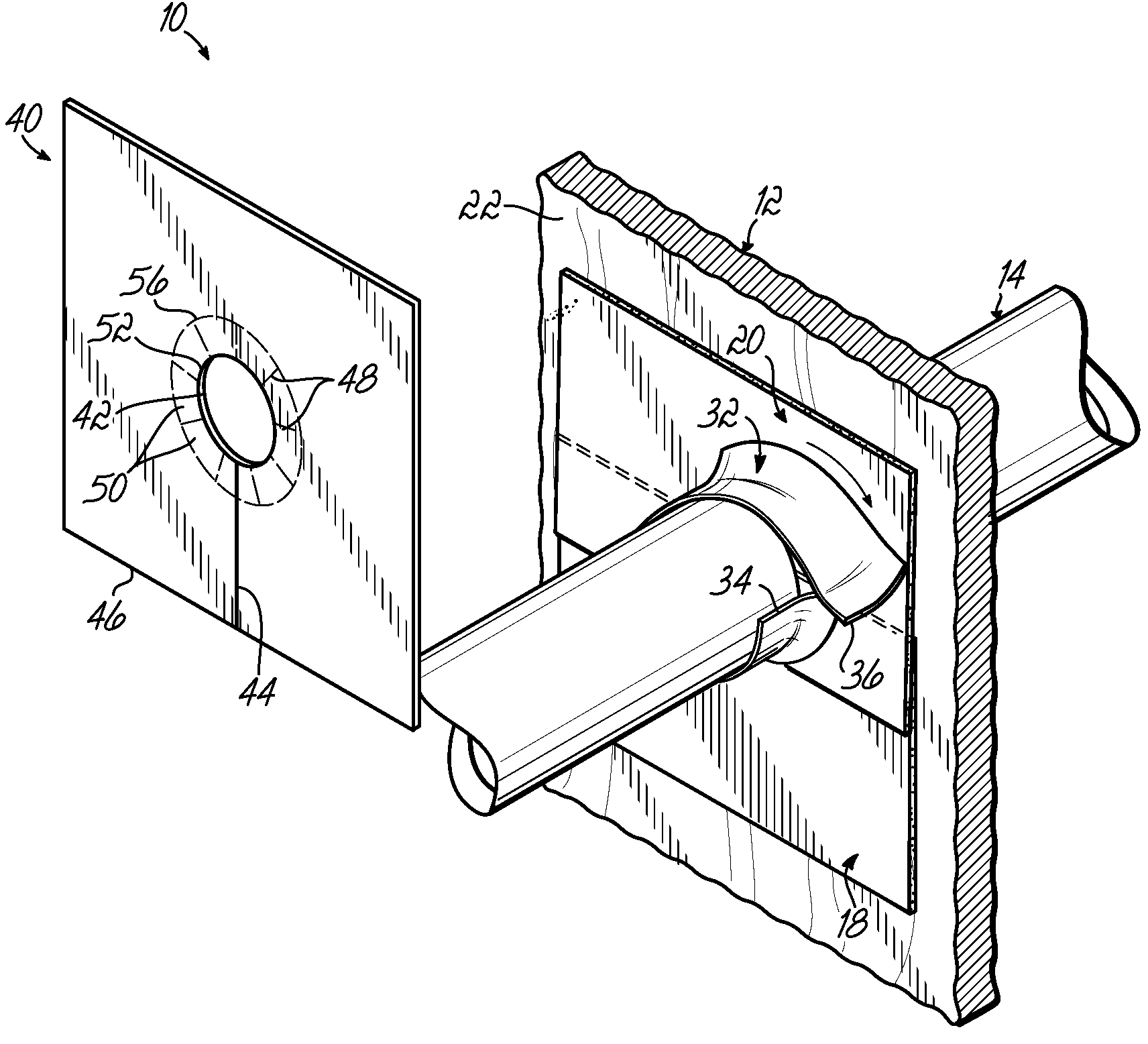
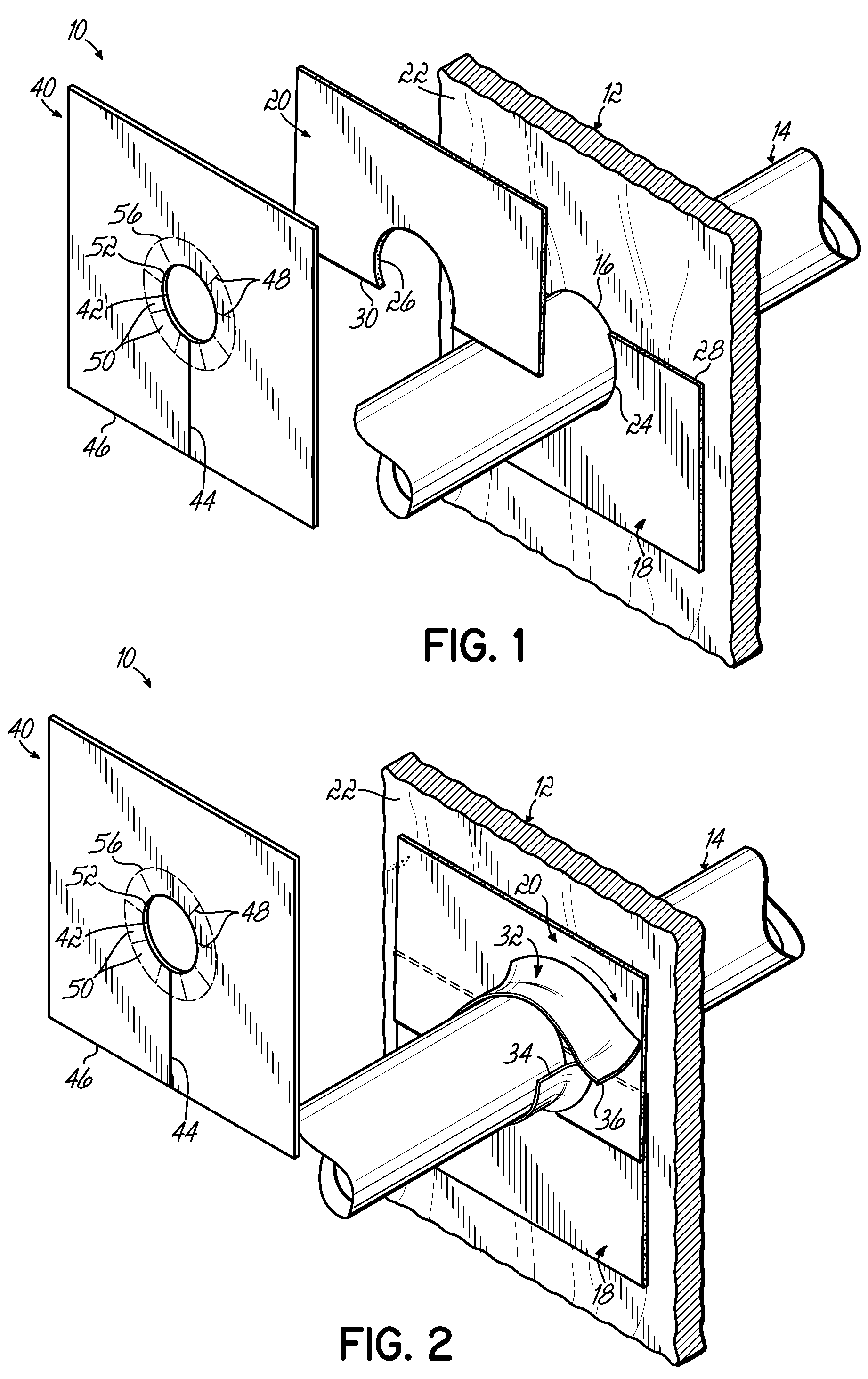
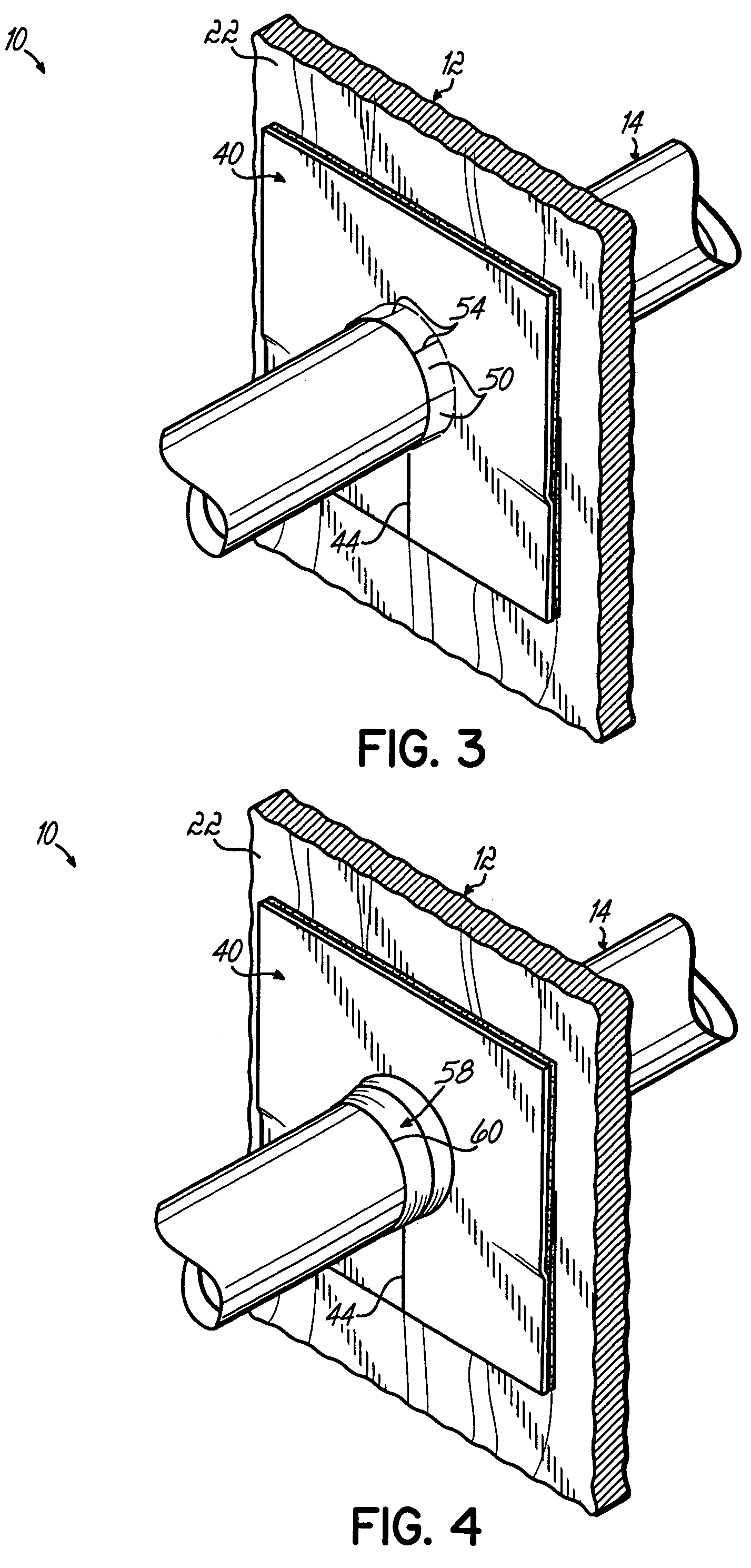
[0019]Referring to FIGS. 1-4, a flashing kit 10 according to one embodiment of this invention is shown being installed at a site on an exterior wall 12 of a building in conjunction with a conduit 14 projecting through a hole 16 in the wall 12. The flashing kit 10 of this invention can be readily used for any penetration through any wall to prevent and inhibit water, moisture, air and foreign elements from passing through the hole in the wall. Moreover, while the conduit 14 is shown with a generally circular cross-sectional configuration, the components of the flashing kit 10 can be readily used and adapted for use with any shape conduit or other element penetrating through any size or shape hole in the wall. The conduit 14 may be used for housing various utilities, such as gas, water, electrical wires, communication wires, telephone wires, or anything else extending through the wall 12.

[0020]The flashing kit 10 according to one embodiment of this invention and as shown in FIGS. 1-4 ...


PUM


Abstract

A flashing kit seals or waterproofs a hole in a wall with a conduit penetrating therethrough. The flashing kit generally includes a first flashing member adapted to be mounted to the wall adjacent the hole, a second flashing member adapted to be mounted to the wall adjacent the hole and the first flashing member, a third flashing member wrapped onto the conduit adjacent the first and second flashing members, and a fourth flashing member adapted to be applied to the wall over the first and second flashing members. The fourth flashing member has an aperture for receiving the conduit and may include one or more leaves spaced about the aperture. The leaves are adapted to bend in order to accommodate the conduit and are covered by a fifth flashing member wrapped around the conduit.

Description

CROSS REFERENCE TO RELATED APPLICATION[0001]This application claims the benefit of and priority to U.S. Provisional Patent Application Ser. No. 60 / 599,122, filed Aug. 5, 2004, and entitled “FLASHING KIT FOR WALL PENETRATIONS,” which is fully incorporated by reference herein.FIELD OF THE INVENTION[0002]This invention relates generally to prohibiting weather-related moisture from entering a building, and more particularly, to a flashing kit for a conduit penetrating through a hole in the exterior wall of a building.BACKGROUND OF THE INVENTION[0003]In the construction of houses, commercial buildings, and the like, various utility / plumbing pipes such as water pipes, gas pipes, drain pipes, HVAC ducts, electrical cables, telephone cables, etc., extend through the walls of the building. When exteriorly terminated, these conduits extend through insulation, between wall boards, potentially within ceiling and floor structures, and in other critical places where a dry environment is extremely...

Claims


Application Information

Patent Timeline
Patent Type & Authority Patents(United States)
IPC IPC(8): E04H12/28E04D1/36
CPCH02G3/22F16L5/02
Inventor COLLINS, P. MICHAEL
Owner TY DAS BUILDING PROD LLC
Why Eureka
Try Eureka