Carton having stacking strength-enhancing feature

a technology of stacking strength and carton, which is applied in the field of cartons, can solve the problems of dispensers, in particular, prone to break open unintentionally, and not all cartons have the strength to physically protect contents, etc., and achieve the effect of facilitating easy access to the articles within the carton and increasing the structural integrity of the carton

Inactive Publication Date: 2009-08-04
MEADWESTVACO PACKAGING SYST LLC
View PDF22 Cites 13 Cited by
  • Summary
  • Abstract
  • Description
  • Claims
  • Application Information

AI Technical Summary

Benefits of technology

[0004]The present invention provides a carton with an improved article dispenser which utilizes end flaps to increase the structural integrity of the carton while continuing to facilitate easy access to the articles within the carton. Flexible and / or deformable articles such as stand-up pouches may be retained within the carton in an organized manner.
[0005]Generally described, top and bottom opposed walls are hingedly interconnected by a pair of side walls to form a tubular body. An end closure structure is provided to at least partially close each end of the tubular body. A buttress arrangement is provided by each end closure structure. Each buttress arrangement is disposed within the interior of the carton and extends vertically between the top and bottom walls to enhance the stacking strength of the carton. An article dispenser is provided at one or both of the opposite ends of the carton. The article dispenser is provided by a removable portion of the carton to define an opening for exposing articles for removal from the carton. The removable portion is defined by a frangible line extending across the top wall at a distance spaced from at least one end of the tubular body. The frangible line further extends from the top wall across each side wall toward the bottom wall to a point on the fold line between each side wall and the bottom wall. The point on each fold line is positioned at a distance from the one end to control undesired tear of the side walls along the frangible line when the carton undergoes vertical compression.
[0011]The present invention in another aspect provides a carton comprising top and bottom opposed walls hingedly interconnected by a pair of side walls to form a tubular body, an end closure structure for at least partially closing each end of the tubular body, and an article dispenser provided at one of the opposite ends by a removable portion of the carton. The removable portion is at least partially defined by a frangible line that comprises first, second, third and fourth portions. The first portion is formed in the top wall and extends between the opposite side edges of the top wall at a distance spaced from the one end. The second portion is formed in one of the side walls and extends from one of the side edges of the top wall to a point on the lower edge of the one side wall. The third portion is formed in the other side wall and extends from the other side edge of the top wall to a point of the lower edge of the other side wall. The fourth portion extends at least partially along the end edge of the bottom wall at the one end of the tubular body such that the second and third portions are interconnected by the fourth portion. Each point on the lower edge of each side wall is positioned at a distance from the one end of the tubular body to control undesired tear of the side walls along the frangible line when the carton undergoes vertical compression.
[0016]The present invention in a still another aspect provides a carton comprising top and bottom opposed walls hingedly interconnected by a pair of side walls to form a tubular body, an end closure structure for at least partially closing each end of the tubular body, and a buttress arrangement provided by each end closure structure. Each buttress arrangement is disposed within the interior of the carton and extends vertically between the top and bottom walls to enhance the stacking strength of the carton. Each end closure structure comprises a pair of side end flaps joined to the side walls respectively. Each side end flaps of each end closure structure comprises a pair of proximal and distal portions. The proximal portion is hingedly connected to the respective side wall whereas the distal portion is hingedly connected to the respective proximal portion. The proximal portions of the side end flaps extend from the side walls toward each other while the distal portions extending from the respective proximal portions into the interior of the carton. These distal portions are disposed in a face-to-face contacting relationship with each other to form the respective buttress arrangement. Each side end flap includes a vertical fold line dividing that side end flap into the distal and proximal portions. The distal portion has a horizontal transverse size greater than that of the proximal portion.

Problems solved by technology

Such articles tend to get easily rearranged and crushed within the carton.
Moreover, not all cartons have sufficient strength to physically protect the contents when arranged in a stacked condition.
Dispensers, in particular, tend to break open unintentionally when the cartons are subject to compression.

Method used


Image

  • Carton having stacking strength-enhancing feature
  • Carton having stacking strength-enhancing feature
  • Carton having stacking strength-enhancing feature

Examples


Embodiment Construction

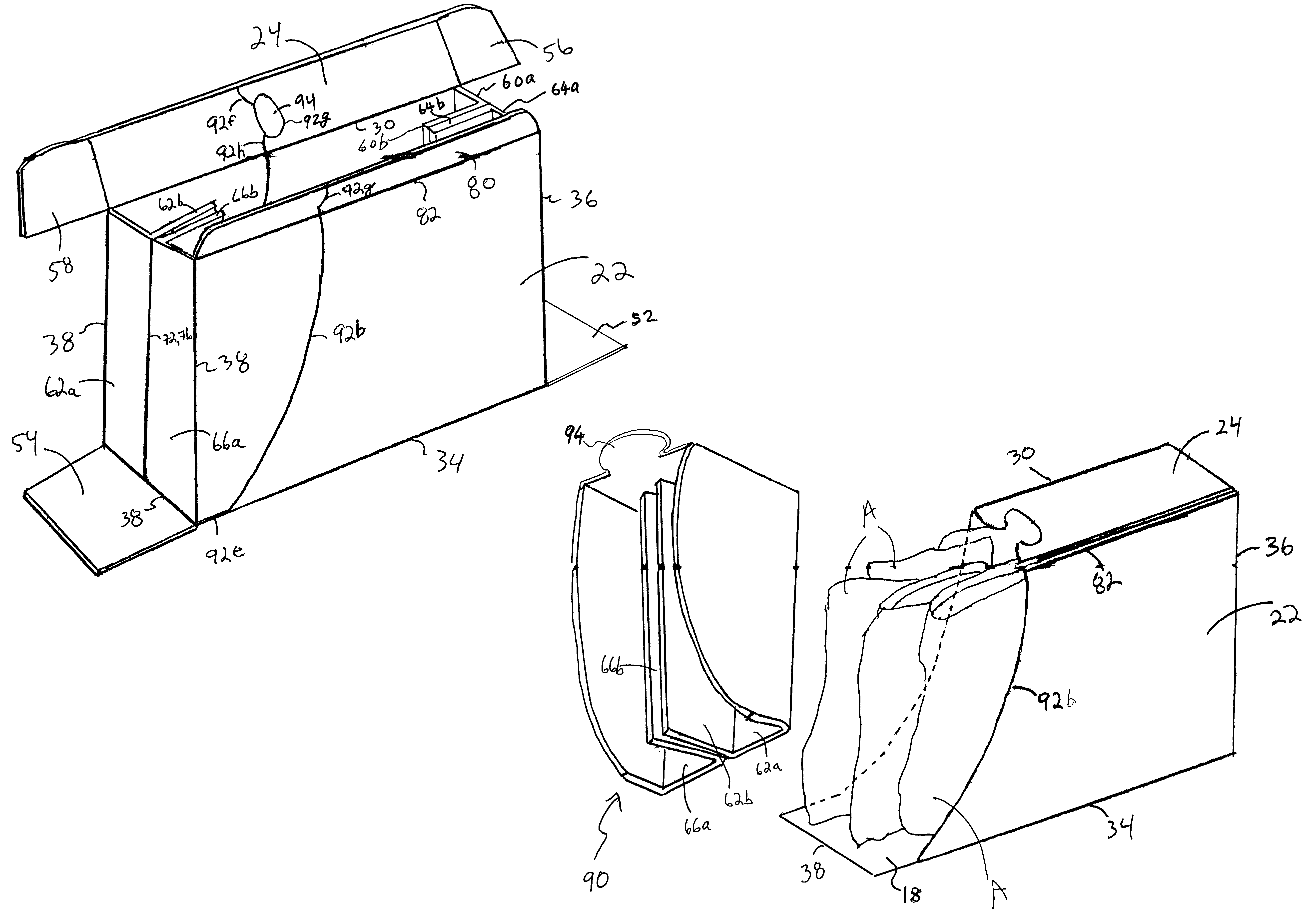
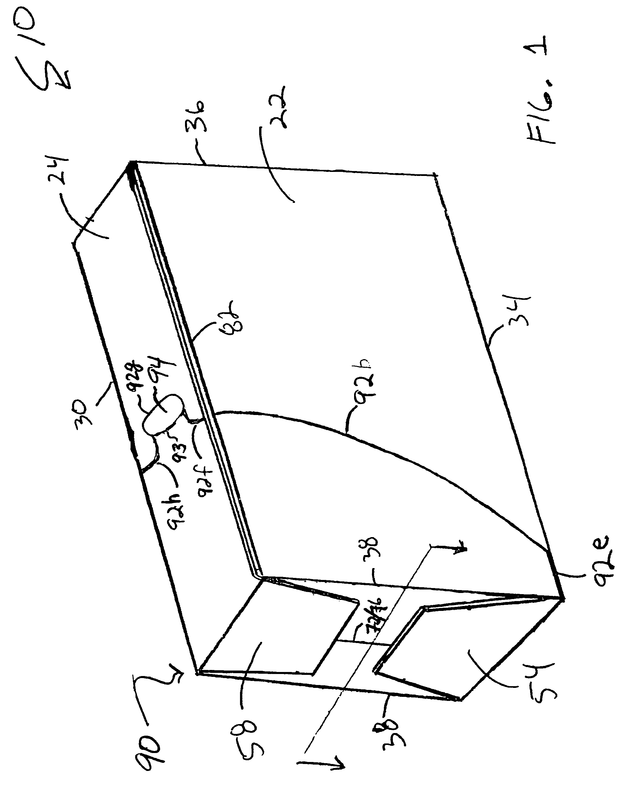
[0028]Referring now to the drawings in which like numerals indicate like elements throughout the several views, the drawings illustrate exemplary embodiments of cartons 10 (FIG. 1) and 12 (FIG. 9) of the present invention. In these embodiments, the cartons 10 and 12 are designed for packaging and dispensing articles “A” which may be beverage pouches made, for example, of a plastic-aluminum laminated film. An example of such a pouch is disclosed in U.S. Pat. No. 5,927,498 which is hereby included by reference.

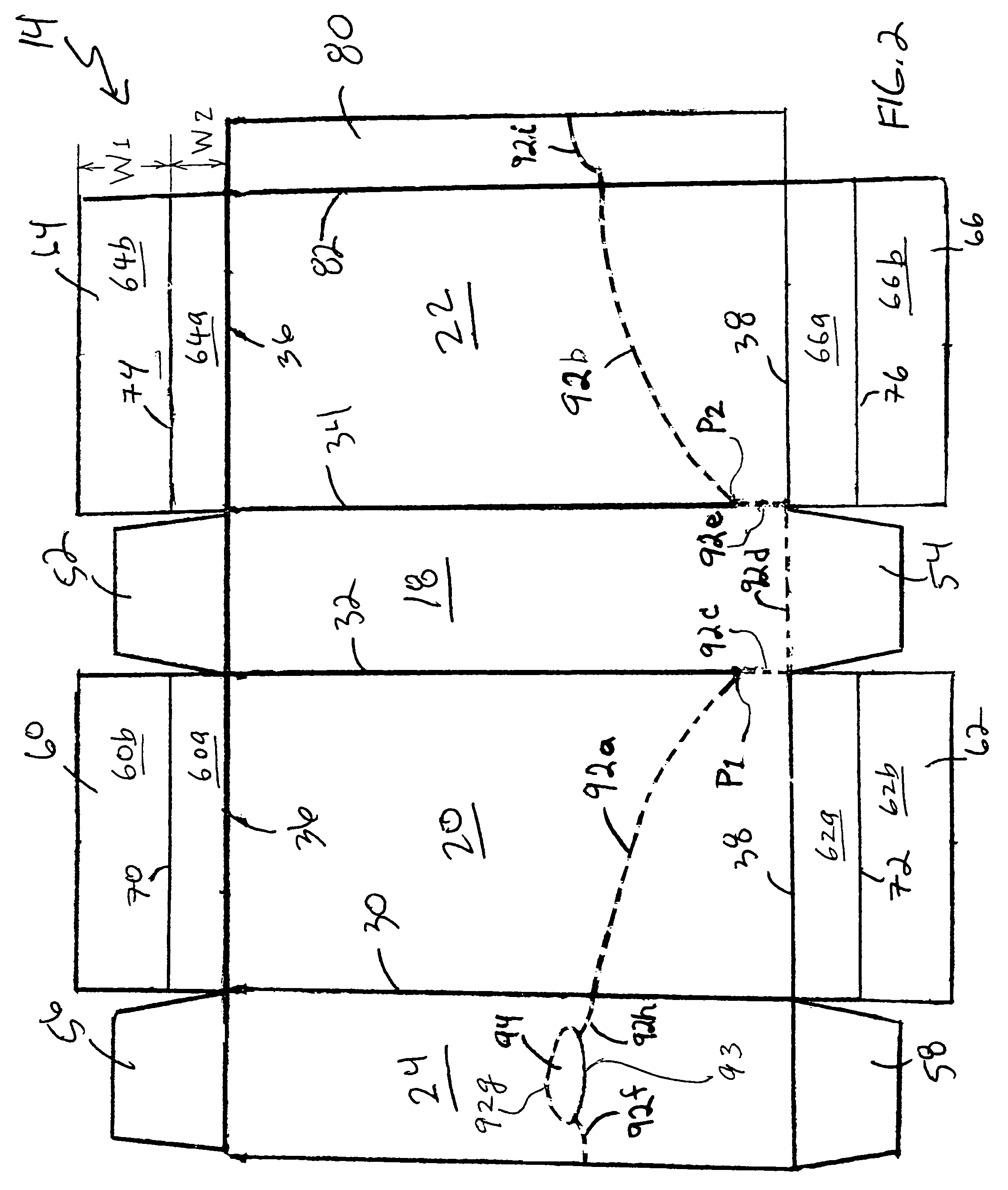
[0029]Generally described, the cartons 10, 12 are formed from foldable sheet material such as paperboard. Carton 10 shown in FIG. 1 is formed from a single blank 14. The blank 14 is configured as shown in FIG. 2 and includes at least four primary panels for forming the carton 10. The primary panels of the blank 14 are a top wall 24, a first side wall 20, a bottom wall 18 and a second side wall 22. These panels 24, 20, 18 and 22 are hingedly connected in series one to the next al...


PUM

PropertyMeasurementUnit
stacking strengthaaaaaaaaaa
sizeaaaaaaaaaa
distanceaaaaaaaaaa

Abstract

A carton having a dispensing feature adapted for permitting the removal of articles from within the carton. Top and bottom opposed walls are interconnected by a pair of side walls to form a tubular body. An article dispenser is provided by a removable portion defined by an opening in the carton for exposing articles for removal. The removable portion is at least partially defined by a frangible line extending across each side wall to opposite side edges of the bottom wall. A portion of the frangible line extends at least partially along the adjacent end edge of the bottom wall and then extends to the opposite side edges of the bottom wall. A buttress arrangement for enhancing the stacking strength of the carton is formed from the distal portion of at least one side end flap.

Description

TECHNICAL FIELD[0001]The present invention relates generally to cartons for use in packaging articles and, more particularly, relates to a dispensing carton whose stacking strength is enhanced by a special arrangement of an end closure structure and / or a frangible line.BACKGROUND OF THE INVENTION[0002]Cartons are useful for allowing consumers to purchase, transport and store a desired quantity of articles. For the convenience of the consumers, some cartons have dispensers which allow the articles to be dispensed from the carton while continuing to encase the remaining articles. A portion of the carton is torn out to form an opening from which articles may be removed.[0003]However, some articles are flexible and / or deformable such as juice pouches. Such articles tend to get easily rearranged and crushed within the carton. Moreover, not all cartons have sufficient strength to physically protect the contents when arranged in a stacked condition. Dispensers, in particular, tend to break...

Claims


Application Information

Patent Timeline
Patent Type & Authority Patents(United States)
IPC IPC(8): B65D25/04B65D17/28B65B5/02B65D5/18B65D5/44B65D5/50B65D5/54B65D71/00B65D71/36
CPCB65D5/18B65D5/443B65D5/5023B65D5/548B65D71/36B65D2571/00839B65D2571/00308B65D2571/00462B65D2571/00574B65D2571/0066B65D2571/00728B65D2571/00141Y10S229/915
Inventor CARGILE, JR., JOHN W.
Owner MEADWESTVACO PACKAGING SYST LLC
Why Eureka
Try Eureka