Level wind mechanism

a level wind and winding technology, applied in the direction of hoisting equipment, fishing, transportation and packaging, etc., can solve the problems of affecting the efficiency of the entire drive mechanism, and affecting the efficiency of the whole drive mechanism

Inactive Publication Date: 2009-08-04
KORE GEAR
View PDF30 Cites 16 Cited by
  • Summary
  • Abstract
  • Description
  • Claims
  • Application Information

AI Technical Summary

Benefits of technology

[0014]Because the line guides are able to remain in driving contact through their entire range of pivot, it is a further intention of the present invention to eliminate the requirement that the level-wind guides be first disengaged from their motive force in order to be shifted to the second position.
[0015]Still further, because the line guides are able to remain in driving contact through their entire range of pivot, it is a further intention of the present invention to eliminate the requirement that the level-wind guides be locked into the second position, and then unlocked again to return to the first position.
[0016]It is a further intention of the present invention to provide a means to enable that the line that has been wound upon a spool can be paid out again without the requirement that the spool revolve in a direction counter to that of line-retrieval. This is accomplished by supporting the spool from only one end. Thus, when the line is to be dispensed, the separate line guides are capable of pivoting to opposite sides of the spool so that the line can be slipped out over the open (unsupported) end of the spool. This eliminates the requirement that the spool revolve in a direction counter to line retrieve in order to dispense the line.
[0017]The novel design of the present invention is also advantageous over the prior art in that because the level-wind guides are capable of remaining in driving contact at all times as they traverse the length of the spool in the first position, and throughout their entire range of pivot to the second position, it is possible to incorporate a compliance or tolerance device to eliminate mechanical failure that is so prevalent of all designs in the prior art. Therefore, it is still a further intention of the present invention to provide for a tolerance device to prevent failure of the level wind components, to prevent failure of their various engagement / disengagement devices, to prevent failure of the supporting structure(s), and to prevent failure of the of the line.
[0024]The line guide can be selectively positioned between (a) a first line retrieving position wherein the elongated slot of the line is capable of substantially traversing the axial length of the spool in order to evenly distribute the line and (b) a second line dispensing position wherein the line guide is located non-disposed within the spool such that the line is allowed to be paid out (or dispensed) from the spool without interference. The driving mechanism comprises an activation switch for effecting the positioning of the line guide from a first line retrieving position to a second line dispensing position. The line guide remains in second line dispensing position while the switch is activated for dispensing of the line. The line guide remains in driving contact with the driving mechanism as the line guide is positioned between the first line retrieving position and the second line dispensing position. The line guiding mechanism includes a compliancy device to allow the line guide to flex due to forces on the line.
[0025]In still a further embodiment, in a convertible fishing reel selectively positionable between a first line retrieving position wherein the line retrieve is substantially perpendicular to the axial length of the spool, and a second line dispensing position wherein the line payout is substantially parallel to the axial length of the spool, having a main-body chassis housing and a spool chassis, wherein the spool chassis receives a spool, and wherein the spool chassis can be selectively rotated between the first line retrieving position and the second line dispensing position, an improved line guiding mechanism of the invention includes: a pair of line guides, wherein each line guide is coupled at either end to its supporting chassis, and wherein the line guides can be selectively positioned between (1) a first line retrieving position wherein the pair of line guides are positioned in a parallel relationship forming a slot therebetween for capture of the line and oscillation in cooperative arcuate paths in front of the spool to evenly distribute line along the axial length of the spool and (2) a second line dispensing position wherein the pair of line guides separate to either side of the spool in divergent arcuate paths about an axis defined by the line guide's ends. The spool support chassis is selectively rotated about an axis of rotation that is generally disposed within the spool. The pair of line guides remain separated in the second line dispensing position to allow payout of the line without interference. The rotating of the spool support chassis between the first line retrieving position and the second line dispensing position effects positioning of the line guides between the first line retrieving position and the second line dispensing position.

Problems solved by technology

One limitation of existing level-wind mechanisms is that they require the line that is being wound upon the spool to be threaded through an enclosed guide, or a line-guide with sufficient line enclosure so that the line is incapable of accidentally escaping the line-guide device.
This is problematic because it requires a manual, cumbersome, time consuming, and often-expensive sequence in order to thread the line through such a guide.
Further, such an enclosure can also create undesired points of friction between itself and the line that is being wound upon the spool, which can result in degradation of the line.
This is problematic because significant friction between the line and the level-wind mechanism results if the line-guide is not also moved axially along the length of the spool in exactly the same axial rate that the line is being unwound from of the spool.
Thus, powering the drive mechanism in reverse equates to the entire drive mechanism suffering a tremendous efficiency loss as it seeks to maintain harmony with the axial rate with which the line is being dispensed from the spool.
However, while solving the power efficiency loss problem, another significant problem is created.
The axially oscillatory fashion of the line being dispensed from one end of the spool and then the other, through a fixed position line guide leads to excessive points of friction and wear on the line (leading to accelerated failure of the line), diminishes the efficiency with which the line is capable of being dispensed, and can lead to significant overruns or tangles of the line.
Obviously, though, this feature significantly increased the complexity of level-wind mechanisms as it perpetuated the requirement that the line guides be releasably engaged / disengaged from their motive force, manually shifted parallel to the axis of the spool to the second position, releasably locked and unlocked from the second position, returnable to the first position and finally re-engaged to their motive force.
Level-wind mechanism in general sometimes operate under significant forces which exacerbates mechanical failure, but even at modest forces and stresses, the reliable engagement and disengagement mechanisms for the various locking devices of the prior art have proven to be challenging at best.

Method used


Image

  • Level wind mechanism
  • Level wind mechanism
  • Level wind mechanism

Examples


first example

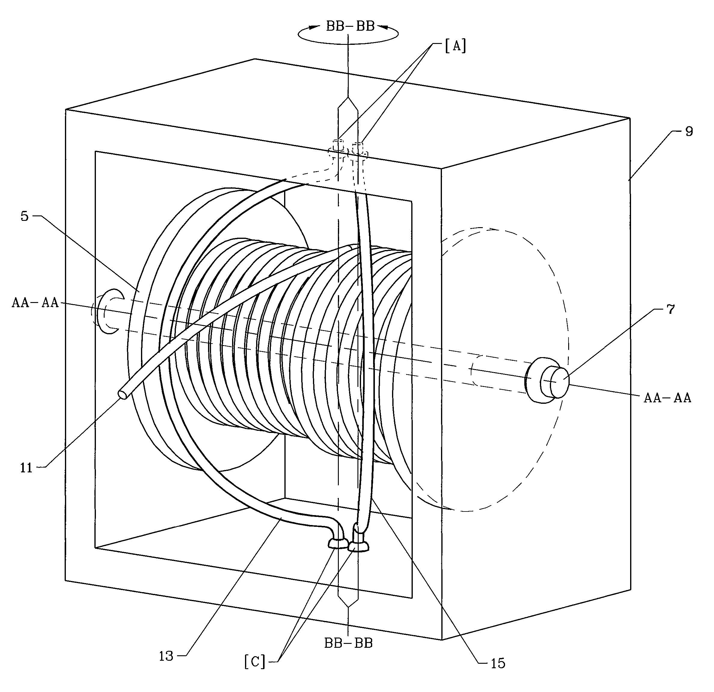
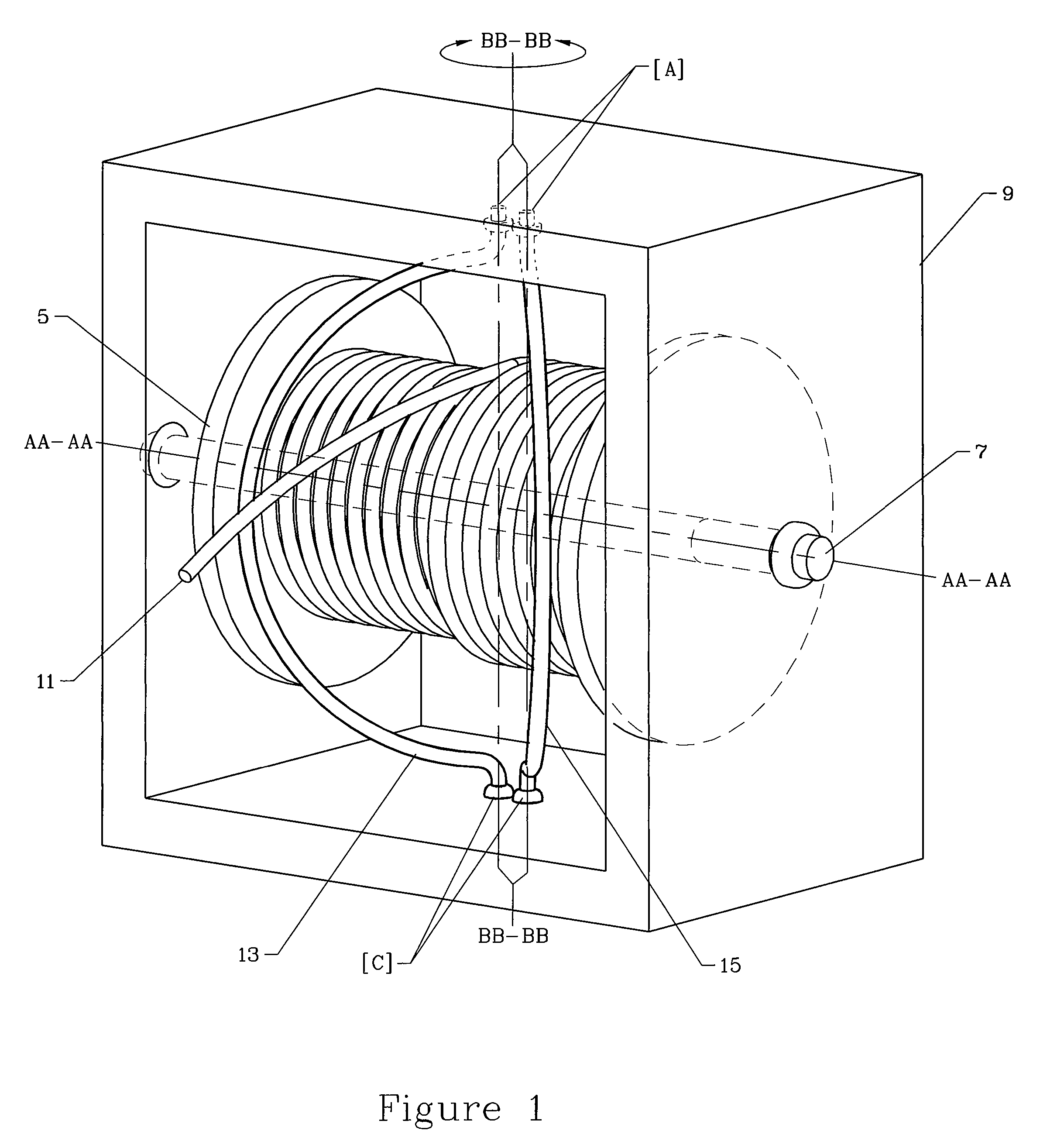
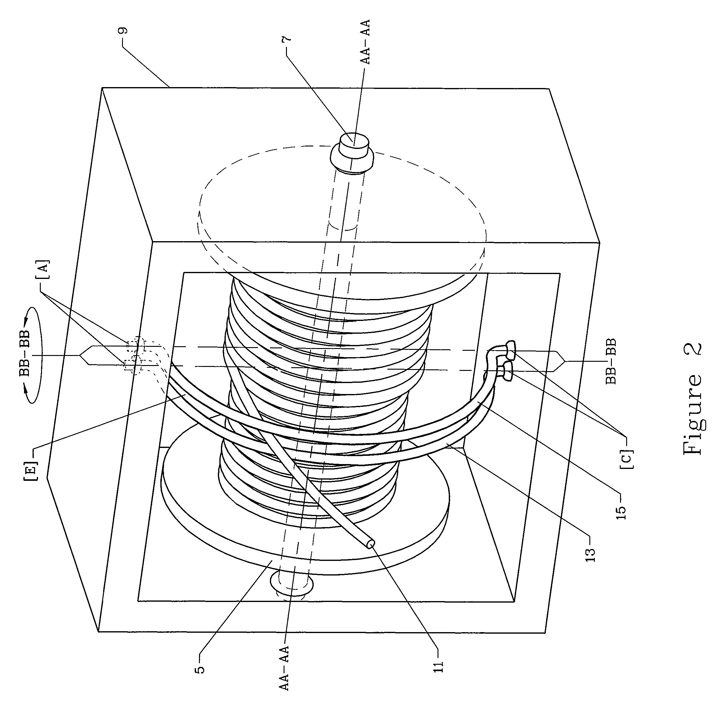
[0062]FIG. 4 is a top view of the present invention with the line guides 13 and 15 pivotally connected to the spool support chassis 9 in at least one position. The line guides 13 and 15 are pivoted together to form the line guide slot E and the line guides 13 and 15, and thus the line 11, are oscillated (about axis BB-BB) to the right-hand axial edge of the spool 5.

[0063]FIG. 5 is a top view of the present invention with the line guides 13 and 15 pivoted together to form the line guide slot E, and showing the line guides 13 and 15 and thus, the line 11 oscillated (about axis BB-BB) back to the left-hand axial edge of the spool 5. Because the line guides 13 and 15 are pivotally supported by the spool support chassis 9, the line guide slot E that is formed between the line guides 13 and 15, travels from the right-hand axial edge of the spool 5 (depicted in FIG. 4) to the left-hand edge of the spool 5 following a path that is arc shaped. Because the line 11 is captured within line guid...

second example

[0088]FIG. 11 is a second example of a top view of the present invention with the line guides 13 and 15 pivoted together to form the line guide slot E and showing the line guides 13 and 15, and thus the line 11 oscillated to the right-hand axial edge of the spool 5.

[0089]FIG. 12 is a top view of the second example of the present invention with the line guides 13 and 15 pivoted together to form the line guide slot E and showing the line guides 13 and 15, and the line 11 oscillated back to the left-hand axial edge of the spool 5. In the second example, the line guides 13 and 15 are pivotally connected to any linear motion device, such that the line guide slot E that is formed between the line guides 13 and 15, travels from the right-hand axial edge of the spool 5 to the left-hand axial edge of the spool 5 (and vice versa) following a linear path. Because the line 11 is captured within the line guide slot E, the line 11 travels from the right-hand axial edge of the spool 5 to the left-...


PUM


Abstract

The present invention provides an alternate design for a level-wind mechanism that eliminates the requirement for the line to be threaded through an enclosed, or multiple device line guide. The present invention guides the line via an open slot created between one or more line guides that pivots about its supporting structure. The line guide(s) oscillate back and forth in concert across the axial length of the spool in order to evenly distribute the line that is being wound upon the spool. Further, the line guide is capable of being pivoted from a first position of line retrieve to a second position of line dissemination when it is desired to pay out the line from the spool.

Description

CROSS-REFERENCE TO RELATED APPLICATIONS[0001]This application claims priority from U.S. provisional application Ser. No. 60 / 673,165, filed Apr. 20, 2005, the disclosure of which is incorporated herein by reference in its entirety.FIELD OF THE INVENTION[0002]The present invention relates to a mechanism to evenly distribute line that is being wrapped upon a spool that is being revolved about its axis. More specifically, the present invention relates to a mechanism that eliminates the requirement of an enclosed line guide in order to distribute the line equally across the axial length of the spool. Elimination of this requirement increases operational efficiency, reduces friction between the line and the guide, allows the line to be paid out from the spool more effectively, eliminates the requirement that the spool revolve counter to the direction of line retrieval in order to enable the line to be dispensed from the spool, etc. This invention is equally suitable for, but not limited t...

Claims


Application Information

Patent Timeline
Patent Type & Authority Patents(United States)
IPC IPC(8): B65H27/00
CPCA01K89/0114B66D1/38A01K89/06A01K89/015
Inventor BARKER, CRAIG H.
Owner KORE GEAR
Why Eureka
Try Eureka