Rear frame structure for vehicle

a rear frame and vehicle technology, applied in the direction of roofs, transportation and packaging, vehicle arrangements, etc., can solve the problems of difficulty in satisfactorily deformation of diagonal members to absorb impact load, and achieve the effect of reliably increasing the vertical dimension of the pressure-receiving surfa

Inactive Publication Date: 2009-08-04
HONDA MOTOR CO LTD
View PDF2 Cites 31 Cited by
  • Summary
  • Abstract
  • Description
  • Claims
  • Application Information

AI Technical Summary

Benefits of technology

[0012]An object of the present invention is to provide a rear frame structure of a vehicle whereby an impact load can be satisfactorily absorbed.
[0013]Another object of the present invention is to provide a rear frame structure of a vehicle whereby a battery and other electrical components provided to the rear of the vehicle body can be protected.

Problems solved by technology

However, since the left and right diagonal members extend in a straight line, when an impact load acts on the rear of the vehicle body, it is difficult for the diagonal members to satisfactorily deform to absorb the impact load.

Method used


Image

  • Rear frame structure for vehicle
  • Rear frame structure for vehicle
  • Rear frame structure for vehicle

Examples


first embodiment

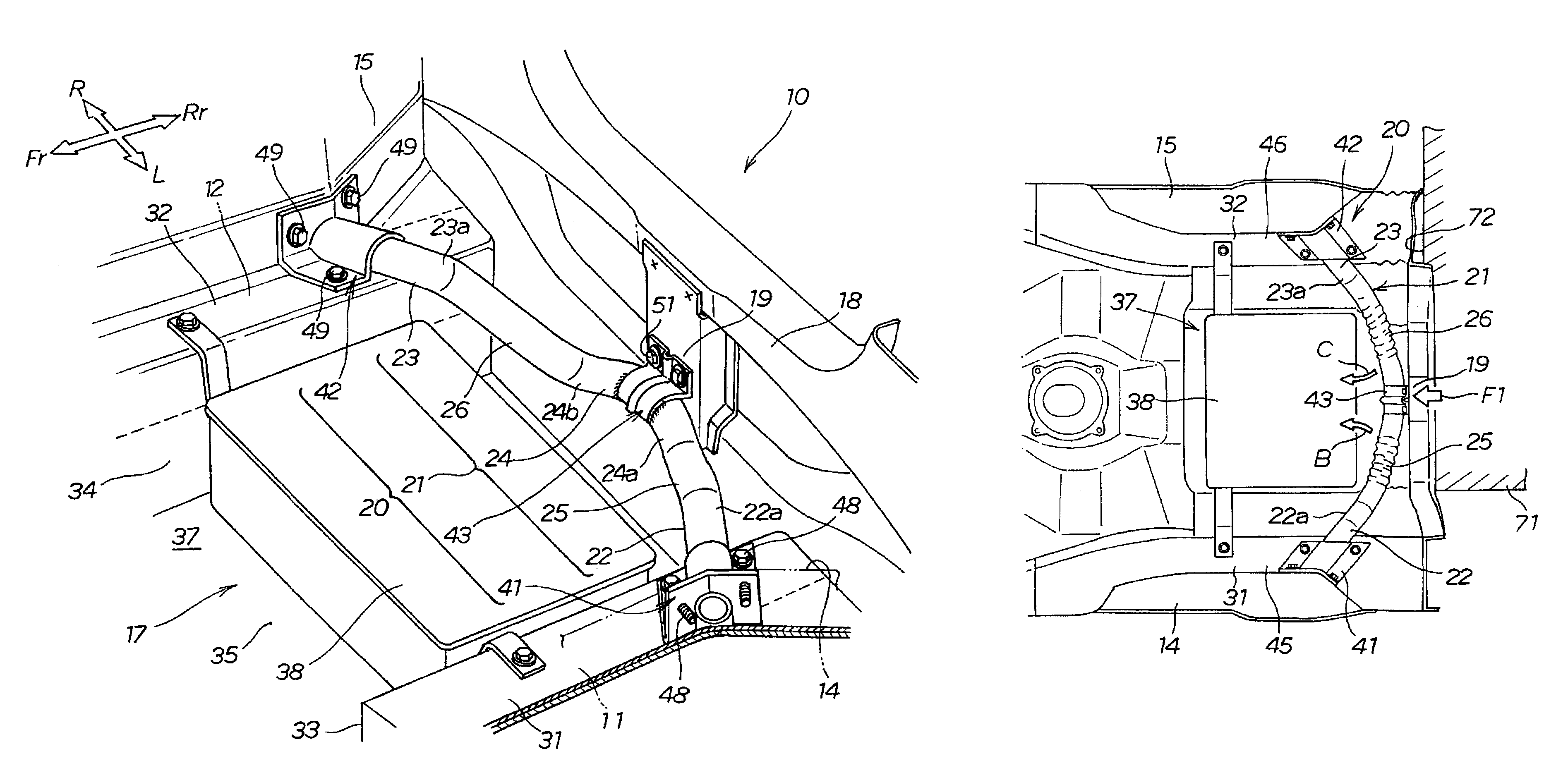
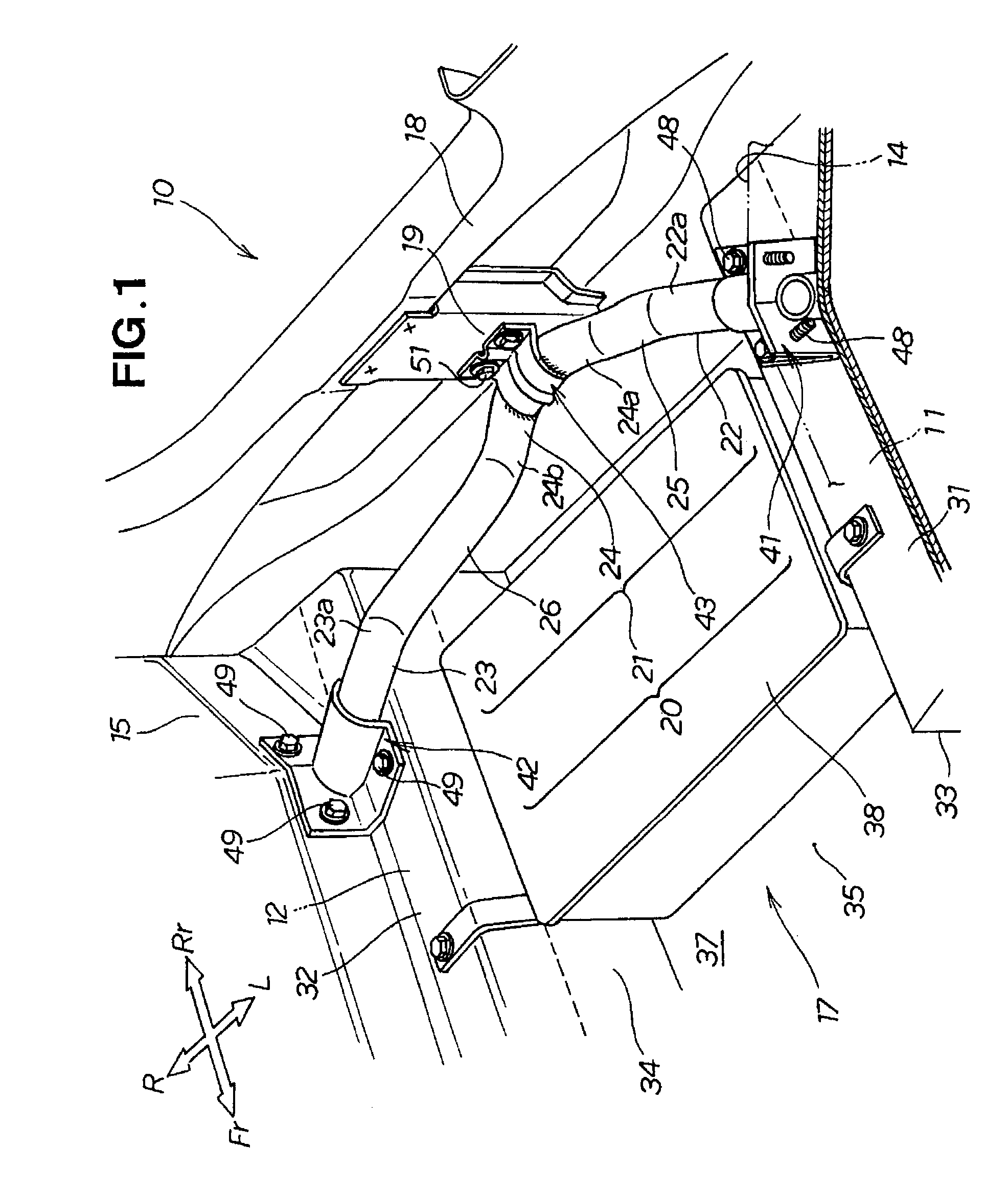
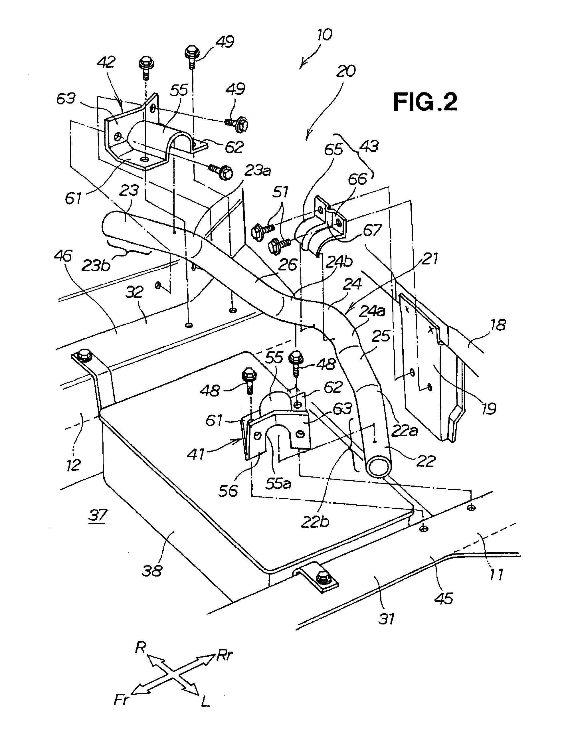
[0044]First, a rear frame structure 10 of the first embodiment will be described with reference to FIGS. 1 through 6D.

[0045]Referring to FIG. 1, the rear frame structure 10 for a vehicle of the first embodiment includes left and right rear frames 11, 12 disposed along the longitudinal direction of the vehicle body, left and right rear wheel houses 14, 15 provided to the left and right rear frames 11, 12, a rear floor 17 provided between the left and right rear frames 11, 12, a rear end panel 18 provided at the rear end of the left and right rear frames 11, 12 and the rear end of the rear floor 17, and impact-absorbing means 20 provided between the left and right rear frames 11, 12, in front of the rear end panel 18 with respect to the vehicle body.

[0046]The left rear wheel house 14 houses a left rear wheel and a left rear damper (not shown). The right rear wheel house 15 houses a right rear wheel and a right rear damper (not shown).

[0047]A left mounting side part 31 is disposed on t...

second embodiment

[0127]Next, a rear frame structure 100 of the second embodiment will be described with reference to FIGS. 7 through 11C.

[0128]Referring to FIG. 7, the rear frame structure 100 of the second embodiment includes left and right rear frames 111, 112 disposed along the longitudinal direction of the vehicle body, left and right rear wheel houses 114 (the right rear wheel house is not shown) provided to the left and right rear frames 111, 112, a rear floor panel 117 provided between the left and right rear frames 111, 112, a rear end panel 118 provided at the rear ends of the left and right rear frames 111, 112 and the rear end of the rear floor panel 117, and impact-absorbing means 120 provided between the left and right rear frames 111, 112.

[0129]The rear frame structure 100 further includes cross members 131, 132 disposed at specific intervals in front of the rear floor panel 117. The cross members 131, 132 span the distance between the left and right rear frames 111, 112.

[0130]The left...


PUM


Abstract

A rear frame structure for a vehicle is disclosed, wherein an impact load can be satisfactorily absorbed in the case of a collision with a rear surface of the vehicle. The rear frame structure includes a pipe-shaped impact-absorbing member located between left and right rear frames. The impact-absorbing member has a center pipe that has a V shape in plan view, formed so as to protrude backward. The impact-absorbing member has left- and right-side pipes extending from the center pipe linearly upwardly to left and right end pipes. The impact load applied to the center pipe causes the left- and right-side pipes to undergo compressive deformation in their axial longitudinal directions as well as bending deformation towards the front of the vehicle body, whereby the impact load is absorbed.

Description

FIELD OF THE INVENTION[0001]The present invention relates to a rear frame structure for a vehicle, which includes left and right rear frames provided with rear wheel houses, and rear end panels provided behind the left and right rear frames.BACKGROUND OF THE INVENTION[0002]In one known rear frame structure, a reinforcing member is provided to the rear frame of a vehicle, as is disclosed in JP 2005-119358 A. The reinforcing member is designed to cope with an impact load when an impact load (impact energy) acts on the rear part of a vehicle body in an offset collision when the vehicle is traveling at low speeds.[0003]The rear frame structure in JP 2005-119358 A includes left and right rear frames extending along the longitudinal direction of the vehicle body, a cross member extending between the left and right rear frames, and a rear end panel spanning between the rear ends of the left and right rear frames.[0004]Left and right diagonal members extend in a straight line from regions w...

Claims


Application Information

Patent Timeline
Patent Type & Authority Patents(United States)
IPC IPC(8): B62D25/08
CPCB62D21/152
Inventor IMADA, SHINICHIABO, MANABUKURATA, HIDETOSHIMATSUURA, NORIKAZUSAITO, YUMI
Owner HONDA MOTOR CO LTD
Why Eureka
Try Eureka