Catheter for uniform delivery of medication

a catheter and uniform technology, applied in the field of catheters, can solve the problems of uneven fluid flow rate through the exit hole, uneven fluid flow rate, and inability to provide uniform fluid flow along the infusion section of the catheter, etc., and achieve the effect of uniform rate, convenient manufacturing and advantageous simplicity

Inactive Publication Date: 2009-08-04
AVENT INC
View PDF50 Cites 31 Cited by
  • Summary
  • Abstract
  • Description
  • Claims
  • Application Information

AI Technical Summary

Benefits of technology

[0013]Accordingly, it is a principle object and advantage of the present invention to overcome some or all of these limitations and to provide an improved catheter for delivering fluid medication to a wound area of an anatomical region.
[0014]In accordance with one embodiment the present invention a catheter is provided for the uniform delivery of fluid across an anatomical region, comprising an elongated tubular member made of a porous membrane. The membrane is sized to be inserted through a subcutaneous layer surrounding the anatomical region, such as a person's skin. The membrane is configured so that a fluid introduced under pressure into an open end of the tubular member will flow through side walls of the tubular member at a substantially uniform rate along a length of the tubular member. The present invention also provides a method of uniformly delivering fluid throughout an anatomical region, comprising the steps of inserting the elongated tubular member into the anatomical region and introducing a fluid under pressure into an open end of the tubular member.
[0015]Another embodiment of the present invention provides a catheter and method for the uniform delivery of fluid throughout an anatomical region. The catheter comprises an elongated support and a porous membrane wrapped around the support. The support is configured so that one or more lumens are formed between the support and the membrane. Alternatively, the support may be a tubular member having a plurality of holes therein. The method comprises the steps of inserting the above-described catheter into the anatomical region and introducing a fluid under pressure into the proximal end of at least one of the lumens. Advantageously, the fluid passes through the membrane at a substantially uniform rate into the anatomical region. The present invention further provides a method of manufacturing this catheter comprising the steps of forming an elongated support and wrapping a porous membrane around the support so that one or more lumens are formed between the support and the membrane.
[0016]Another embodiment of the present invention provides a catheter and method for the uniform delivery of fluid throughout an anatomical region. The catheter comprises an elongated tube including a plurality of exit holes along a length thereof and a tubular porous membrane concentrically enclosed within the tube. The tube and membrane define a lumen. The method comprises the steps of inserting the above-mentioned catheter into the anatomical region and introducing a fluid under pressure into the proximal end of the lumen so that the fluid advantageously passes through the membrane and the exit holes at a substantially uniform rate into the anatomical region. The present invention further provides a method of manufacturing this catheter, comprising the steps of forming an elongated tube, providing a plurality of exit holes along a length of the tube, forming a tubular porous membrane, and concentrically enclosing the tubular porous membrane within the tube so that the tube and membrane define a lumen.
[0017]Yet another embodiment of the present invention provides a device and method for the uniform delivery of fluid throughout an anatomical region. The device is advantageously simple and easy to manufacture, comprising an elongated catheter having a plurality of exit holes along a length thereof. The exit holes may serve as the flow-restricting orifice. Alternatively, a flow-restricting orifice may be provided elsewhere within the catheter or proximal to the catheter. The exit holes may gradually increase in size along the length of the catheter, so that the largest exit hole is further distal than the smallest exit hole. Alternatively, the holes can be laser drilled and be of approximately the same size. Advantageously, a fluid flowing under pressure within the catheter will flow through substantially all of the exit holes at a substantially equal rate. The method comprises the steps of inserting the catheter into the anatomical region and introducing a fluid under pressure into the proximal end of the catheter. The fluid flows through the exit holes and enters the anatomical region, advantageously flowing through substantially all of the exit holes at a substantially equal rate. The present invention further provides a method of manufacturing this device, comprising the steps of forming an elongated catheter and providing a plurality of exit holes along a length of the catheter in a manner so that the exit holes gradually increase in size along the length of the catheter from the proximal end to the distal end thereof.
[0018]Yet another embodiment of the present invention provides a catheter and method for delivering fluid medication to an anatomical region. The catheter comprises a tube, a “weeping” tubular coil spring attached to a distal end of the tube, and a stop closing a distal end of the spring. The tube and spring each define a portion of a central lumen. The spring has adjacent coils in contact with one another so that fluid within the spring and below a threshold dispensation pressure is prevented from exiting the lumen by flowing radially between the coils. The spring has the property of stretching when the fluid pressure is greater than or equal to the threshold dispensation pressure permitting the fluid to be dispensed from the lumen by flowing radially between the coils, i.e. “weeping” through the spring. Alternatively, the fluid may weep through imperfections in the spring coil. Advantageously, the fluid is dispensed substantially uniformly throughout the length and circumference of a portion of the spring. In use, fluid is introduced into an open proximal end of the tube, allowed to flow into the spring, and brought to a pressure greater than or equal to the threshold dispensation pressure so that the fluid weeps through the spring.

Problems solved by technology

Unfortunately, a limitation of prior art catheters with multiple exit holes, such as the catheter taught by Eldor, is that during low pressure delivery of fluid medication the fluid tends to exit only through the exit hole(s) nearest to the proximal end of the infusion section of the catheter tube.
Also, even in those cases in which high pressure fluid delivery is acceptable or desirable, prior art catheters do not provide for uniform fluid delivery along the infusion section of the catheter.
As a result, there is an uneven distribution of medication throughout the wound area.
One disadvantage is that the fluid flow rates through the exit holes are not equal, since the more distal exit holes offer a greater flow resistance for the same reasons discussed above.
Another disadvantage is that the number of lumens, and consequently the number of fluid exit holes, is limited by the small diameter of the catheter tube.
As a result, fluid may be delivered only to a very limited number of positions within the wound area.
Yet another disadvantage is that the proximal ends of the lumens must be attached to a complicated manifold which increases the cost of manufacturing the catheter.
Unfortunately, the Wang catheter is only effective for relatively high pressure fluid delivery.
When used for relatively low pressure fluid delivery, the catheter disclosed by Wang does not provide uniform dispensation of fluid.
Even for high pressure fluid delivery, there are several limitations of this design.
One limitation is that the concentric tubes design is relatively complex and difficult to manufacture.
Another limitation is that the annular passageway may be disturbed if there is a bend in the infusion section of the tube.
This can cause an uneven fluid pressure within a longitudinal cross-section of the annular passageway, resulting in non-uniform fluid delivery.

Method used


Image

  • Catheter for uniform delivery of medication
  • Catheter for uniform delivery of medication
  • Catheter for uniform delivery of medication

Examples


Embodiment Construction

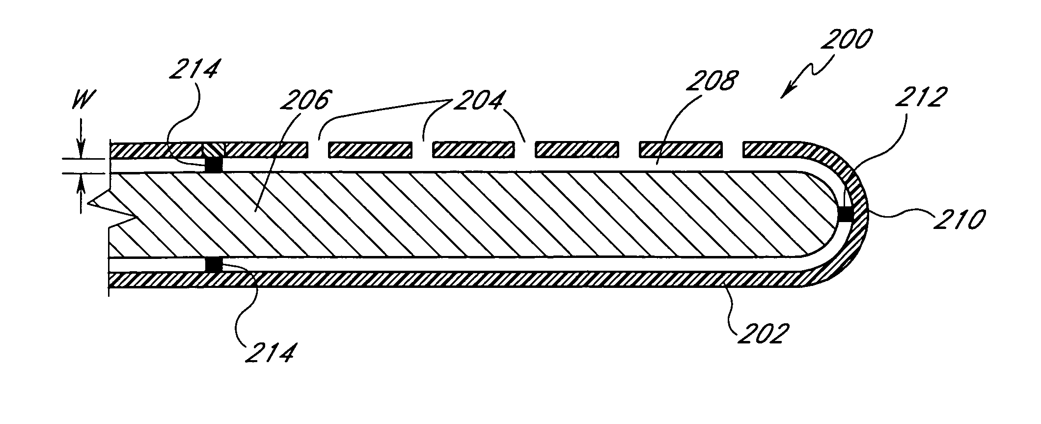
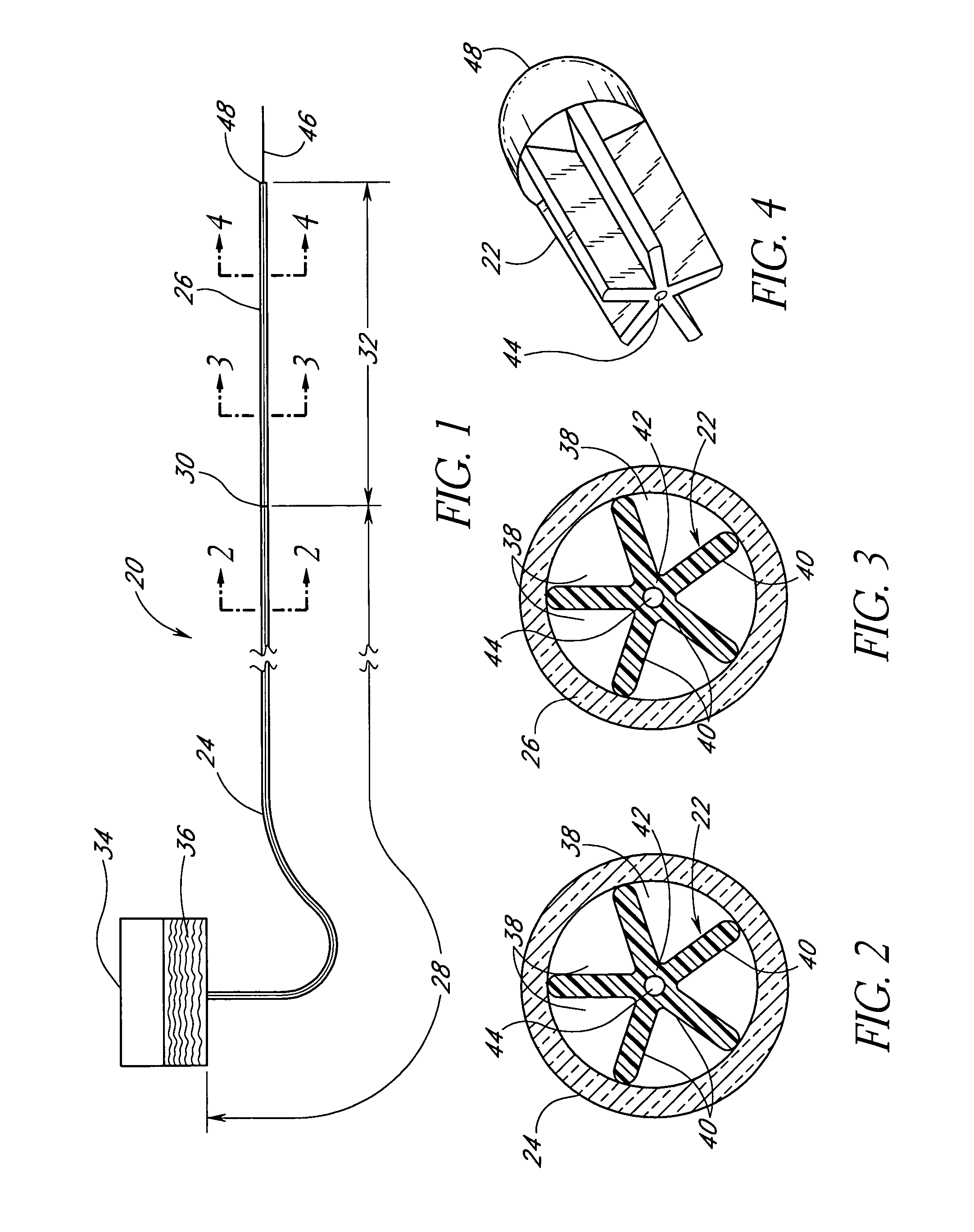
[0045]FIGS. 1-4 illustrate an infusion catheter 20 according to one embodiment of the present invention. Catheter 20 preferably includes a flexible support 22 (FIGS. 2-4), a non-porous membrane 24, and a porous membrane 26. The membranes 24 and 26 are wrapped around the support 22 to form a plurality of axial lumens between the inner surfaces of the membranes 24 and 26 and the surface of the support 22, as described in greater detail below. The non-porous membrane 24 defines a non-infusing section 28 of the catheter 20, and preferably covers the support 22 from the proximal end thereof to a point 30, shown in FIG. 1. Similarly, the porous membrane 26 defines an infusion section 32 of catheter 20, and preferably covers the support 22 from the point 30 to the distal end of support 22. Alternatively, the catheter 20 may be configured without a non-porous membrane 24. In this configuration, the porous membrane 26 covers the entire length of the support 22, so that the entire length of t...


PUM


Abstract

The present invention provides a catheter for the delivery of fluid medication across an anatomical region. In accordance with one embodiment, the catheter comprises an elongated tube with a plurality of exit holes along an infusion section of the catheter, and an elongated flexible porous member residing within the tube and forming an annular space between the tube and the member. In accordance with other embodiments, the catheter includes a tube having a plurality of exit holes in a side wall of the tube. The exit holes may combine to form a flow-restricting orifice of the catheter. Advantageously, fluid within the catheter flows through all of the exit holes, resulting in uniform distribution of fluid within an anatomical region. In one particular embodiment, the catheter comprises a tube having elongated exit slots therein. In accordance with other embodiments, the catheter includes an elongated tubular member made of a porous membrane. The porous membrane is configured so that a fluid introduced into an open end of the tubular member will flow through side walls of the tubular member at a substantially uniform rate along a length of the tubular member. In accordance with other embodiments, the catheter includes an elongated “weeping” tubular coil spring attached to an end of, or enclosed within, a tube. Fluid within the spring and greater than or equal to a threshold pressure advantageously flows radially outward between the spring coils. Advantageously, the fluid is dispensed substantially uniformly throughout a length of the spring.

Description

RELATED APPLICATIONS[0001]This application is a continuation of U.S. patent application Ser. No. 10 / 031,913, filed May 21, 2002, which is the national phase of PCT / US00 / 19746, filed Jul. 19, 2000, which claims priority to U.S. patent application Ser. No. 09 / 363,228 filed Jul. 19, 1999, now U.S. Pat. No. 6,350,253, issued Feb. 26, 2002, the entireties of which are expressly incorporated by reference herein and made a part of this specification.BACKGROUND OF THE INVENTION[0002]1. Field of the Invention[0003]This invention generally relates to catheters and, in particular, to a catheter that delivers fluid medication uniformly across an infusion section of the catheter.[0004]2. Description of the Related Art[0005]Infusion catheters for delivery of fluid medication into anatomical systems, such as the human body, are well known in the art. Such catheters generally include a flexible hollow tube inserted into some region of the anatomy. The tube typically contains one or more axial lumen...

Claims


Application Information

Patent Timeline
Patent Type & Authority Patents(United States)
IPC IPC(8): A61M25/098A61F2/958A61M25/00A61M25/14A61M25/16A61M29/00
CPCA61M25/0043A61M25/0074A61M29/00A61M25/007A61M25/00A61M25/0023A61M25/0068A61M25/0069Y10T156/1028A61M25/10A61M2025/0057A61M2025/0073
Inventor DENIEGA, JOSE CASTILLOMASSENGALE, ROGERRAKE, KENNETH W.
Owner AVENT INC
Why Eureka
Try Eureka