Off-axis anchor guidance system

a technology of anchoring system and guide wire, which is applied in the field of system and method of inserting and guiding bone anchoring devices, can solve the problems of increasing the damage to the surrounding tissue and muscle of the patient, increasing affecting the safety of patients, so as to reduce the risk of fracture, increase the strength of the guide wire, and reduce the effect of kinking

Active Publication Date: 2009-08-04
THEKEN SURGICAL LLC
View PDF205 Cites 101 Cited by
  • Summary
  • Abstract
  • Description
  • Claims
  • Application Information

AI Technical Summary

Benefits of technology

[0012]Thus various aspects of this disclosure allows the shanks of wire guided anchors to resist larger forces than conventional cannulated screws because the offset bores do not cause a cannulation through the entire length of the anchor. Furthermore, the offset bore may be of a relatively larger diameter when compared to the conventional cannulation of conventional cannulated pedicle screws. The larger diameter bore results in a larger diameter guide wire which: increases the strength of the guide wire; reduces kinking; allows a surgeon to have tactile feedback regarding the placement and location of the guide wire; and allows the surgeon to maintain hold of the proximal end of the guide wire at all times throughout the procedure. Furthermore, the relative short length of the offset bore reduces the friction between the instruments and the guide wire, thereby reducing the likelihood of guide wire advancement.

Problems solved by technology

One problem when connecting the rods to the pedicle screws is to position the rods in place as quickly as possible without doing more damage to the surrounding tissue and muscle of the patient.
Once a patient recovers and become active, the brace may be subject to relatively large structural forces.
This causes a significant weakening of the screw.
This weakening can cause failure of the pedicle screw which means that the patient would have to undergo additional surgery to have the pedicle screws replaced.
This means that the guides wires must also be small, which may lead to advancement, kinking, breakage, or other problems during surgery.
This unwanted guide wire advancement could cause the guide wire to push forward through the anterior wall of the vertebral body, causing trauma to the patient.
Furthermore, the relative short length of the offset bore reduces the friction between the instruments and the guide wire, thereby reducing the likelihood of guide wire advancement.

Method used


Image

  • Off-axis anchor guidance system
  • Off-axis anchor guidance system
  • Off-axis anchor guidance system

Examples


Embodiment Construction

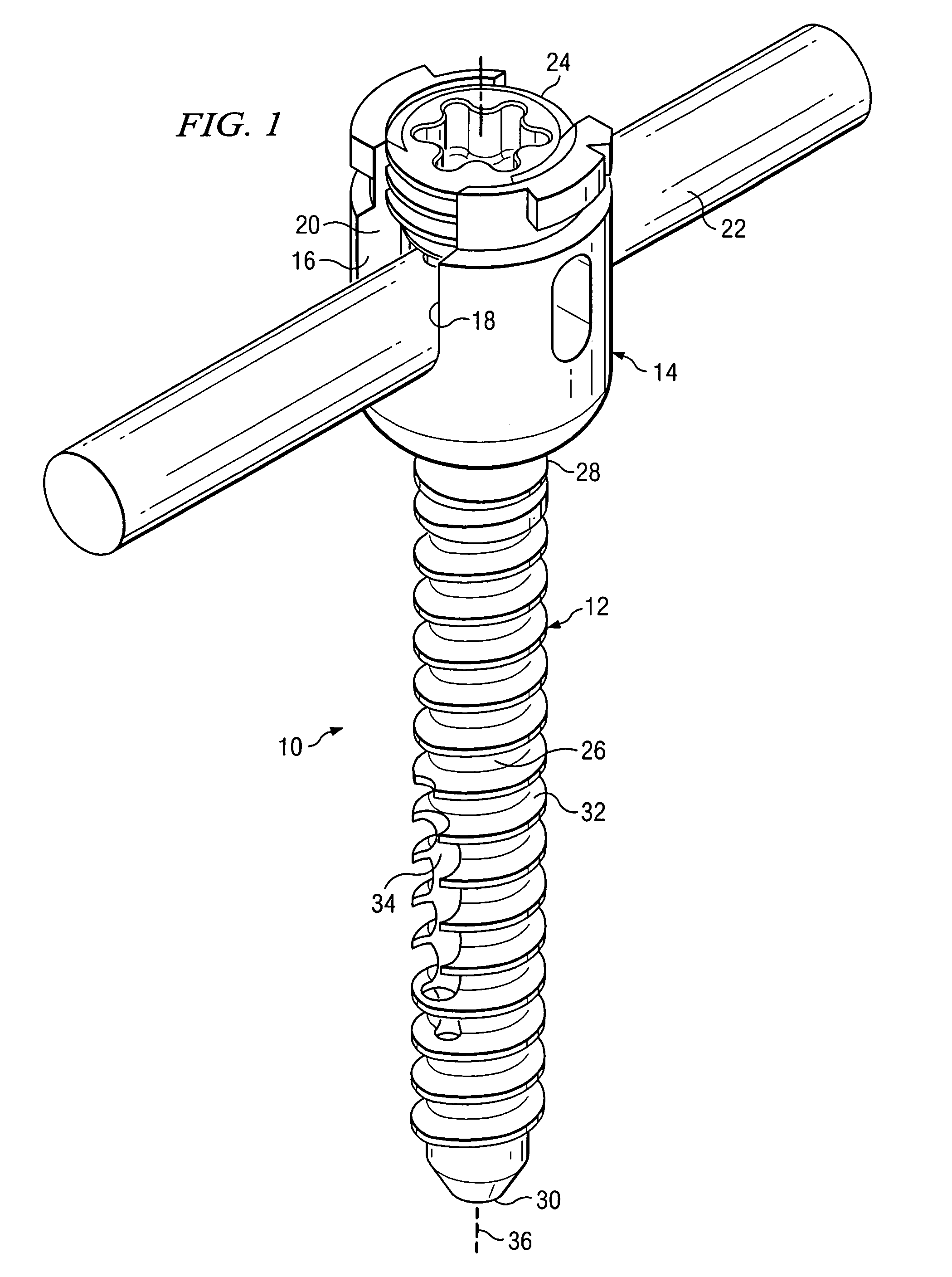
[0029]Turning now to FIG. 1, there is presented one illustrative embodiment of an anchoring system showing certain aspects of the present invention. As shown, a medical implant device 10 includes an anchor 12 which may be coupled to a rod receiving part 14. In some embodiments, the rod receiving part 14 may include noncontiguous walls 16 and 18 which form a channel 20 for receiving a rod 22. In some embodiments, there is a closure member 24 which engages the walls 16 and 18 and thus applies pressure to the rod 22 to effectively clamp about the rod 22, thereby positionally securing the rod 22 relative to the anchor 12. Such a closure member is more fully described in a co-pending and commonly assigned U.S. patent application Ser. No. 10 / 805,967 filed on Mar. 22, 2004 entitled “CLOSURE MEMBER FOR A MEDICAL IMPLANT DEVICE” (hereafter “the '967 patent application), which is hereby incorporated by reference.

[0030]In the illustrated embodiment, the anchor 12 has a shank 26 having a proxim...


PUM


Abstract

Disclosed is a guided bone anchoring device comprising a head, a shank and a passage for receiving a guide wire, the passage having a longitudinal center axis which is not concentric to the longitudinal center axis of the shank. Also disclosed is a system for guiding bone anchors, the system comprising: a guide wire, an anchor comprised of a shank wherein the shank has an offset bore at the distal end which is adapted to allow the guide wire to slide through the bore, a dilator having a longitudinal slot wherein the longitudinal slot allows the guide wire to extend through the longitudinal slot when the anchor is positioned within the dilator, and a driving device which is adapted to engage the proximal end of the anchor.

Description

CROSS REFERENCE TO RELATED APPLICATIONS[0001]This application is a continuation-in-part of patent application Ser. No. 10 / 990,272, entitled “An Implant Assembly And Method For Use In An Internal Structure Stabilization System” filed on Nov. 16, 2004, the disclosure of which is hereby incorporated by reference. This application is related to and claims priority to the following commonly-owned U.S. applications: U.S. application Ser. No. 10 / 989,715, entitled: An Extension for Use with Stabilization Systems for Internal Structures; U.S. application Ser. No. 10 / 989,782, entitled: Connector Transfer Tool for Internal Structure Stabilization Systems; and U.S. application Ser. No. 10 / 990,221, entitled: Internal Structure Stabilization System for Spanning Three or More Structures.TECHNICAL FIELD[0002]This application relates generally to the field of medical implant devices and more particularly to systems and methods for inserting and guiding bone anchoring devices.BACKGROUND INFORMATION[0...

Claims


Application Information

Patent Timeline
Patent Type & Authority Patents(United States)
IPC IPC(8): A61F5/00A61B17/56A61B17/58
CPCA61B17/1735A61B17/1757A61B17/7082A61B17/864
Inventor COLLERAN, DENNIS
Owner THEKEN SURGICAL LLC
Why Eureka
Try Eureka