Filtering particulate materials in continuous emission monitoring systems

a technology of emission monitoring system and filtering particulate materials, which is applied in auxillary pretreatment, instruments, separation processes, etc., can solve the problems of further interrupting the continuous gas monitoring process, reducing or completely restricting the flow of gases to the analyzer, interruptions and delays, etc., to facilitate effective blowback of the sample line

Inactive Publication Date: 2009-08-04
AIR LIQUIDE AMERICA INC
View PDF6 Cites 13 Cited by
  • Summary
  • Abstract
  • Description
  • Claims
  • Application Information

AI Technical Summary

Benefits of technology

[0012]An efficient system and corresponding method are provided to avoid the above-noted problems associated with continuous emissions monitoring caused by filter clogging and requisite blowback procedures. In particular, system and method facilitate effective blowback of a sample line while maintaining a substantially continuous flow of sample to an analyzer section downstream from the sampling line.

Problems solved by technology

Extractive sampling of high density processes (e.g., EAF, glass melters, aluminum furnaces, etc.) often require periodic maintenance due to restriction or plugging that can occur within the sampling line, particularly at the filters, which in turn reduces or completely restricts the flow of gases to the analyzer.
The blowback process further interrupts the continuous gas monitoring process, which can become frequent for high density sample gases which require a shorter time interval between blowback steps to prevent clogging of the sample line.
Interruptions and delays in the sample gas measurements by the analyzer (or analyzers), as well as the above-noted dilutions of the sample gas that can occur, due to blowback processing can become problematic particularly for dynamic processes that require continuous and real-time monitoring.
In addition, for sampling streams containing a high density of particulate materials, other potential problems in the sampling process are possible.
This results in sampling rate variations as well as delays in sampling measurements, which can be detrimental to the sampling process.
However, the particle density of this process is so high that sampling rate variations caused by pressure drop variations across the filter are very likely to occur between blowback processing steps.
When the sampling measurements are coupled to a process control scheme for O2 injection, the variation in sampling can result in undershooting or overshooting the desired O2 concentration in the EAF, which in turn reduces the potential for energy recovery through CO / H2 combustion in the process.

Method used


Image

  • Filtering particulate materials in continuous emission monitoring systems
  • Filtering particulate materials in continuous emission monitoring systems
  • Filtering particulate materials in continuous emission monitoring systems

Examples


Embodiment Construction

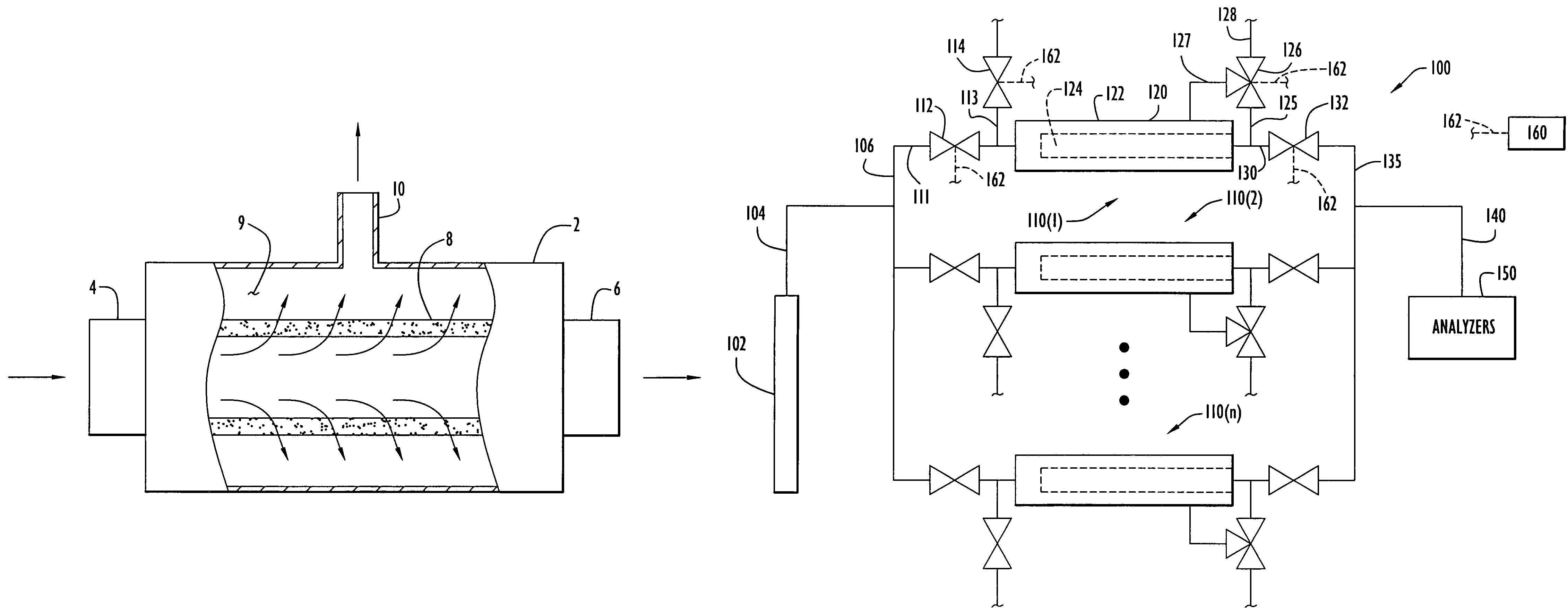
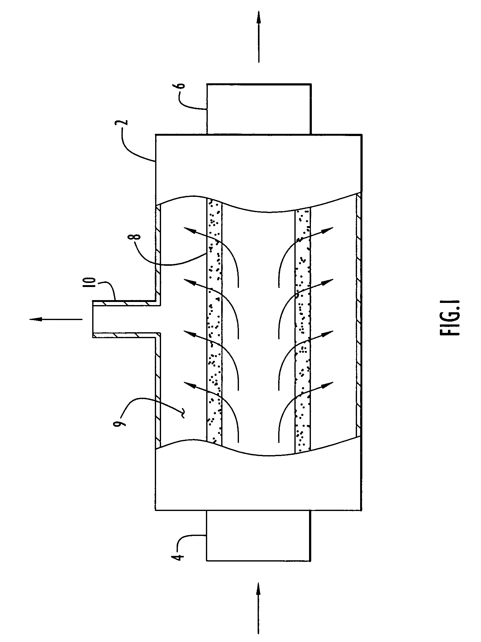
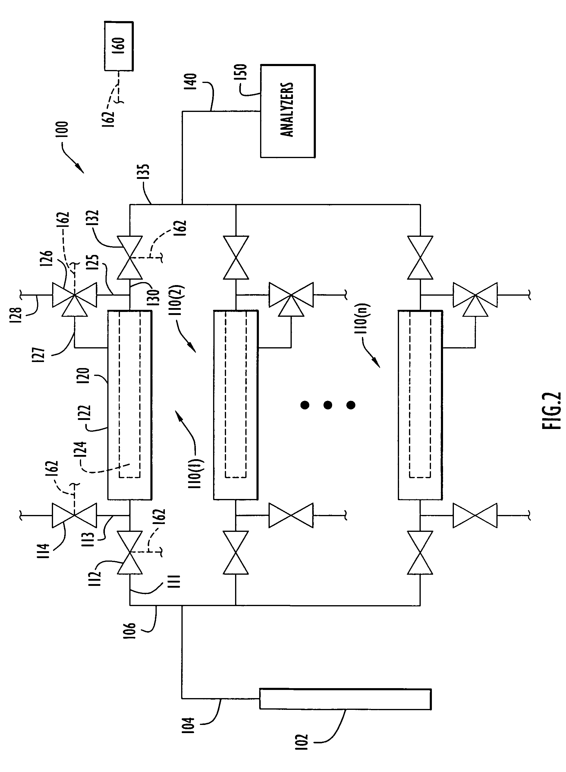
[0019]An extractive sampling system for continuously monitoring gaseous and / or other types of fluid emissions (e.g., liquids) from an application or process includes a main sampling line with a plurality of separate conditioning lines connected in parallel or a multiplexed manner to the main sampling line, where each conditioning line includes a filter to remove particulate materials from a sampled gas stream flowing through the conditioning line.

[0020]The conditioning lines can include any one or more suitable types of filters for filtering particulate materials of selected sizes from the gaseous sample. The filter material can be of any suitable type, such as sintered metal or ceramic materials. The pore size of the filter material can also be of any selected size, such as in the range of about 5 micrometers (microns) to about 50 microns depending upon a particular application. The filter material can also include smaller pore sizes (e.g., 1-2 microns or less) for a particular app...


PUM

PropertyMeasurementUnit
temperatureaaaaaaaaaa
pore sizeaaaaaaaaaa
pore sizesaaaaaaaaaa

Abstract

A filtering system for monitoring fluid emissions from a process includes a plurality of filter assembly sections arranged in a parallel fluid flow manner with respect to each other so as to selectively receive a sample fluid (e.g., a sample gas) entering at an inlet of the system. Each filter assembly section includes a filter unit to filter particulate materials from a fluid flowing through the filter, first and second valves disposed at upstream and downstream locations of the filter unit, and a blowback flow path configured to selectively direct a cleaning fluid through the filter unit in a direction that opposes a direction in which the sample fluid flows through the filter unit. Each filter assembly section can be selectively isolated from other portions of the system so as to prevent the sample fluid from flowing through the filter assembly section while allowing a cleaning fluid to be delivered through the blowback flow path of the filter assembly section.

Description

CROSS-REFERENCE TO RELATED APPLICATIONS[0001]This application claims priority from U.S. Provisional Patent Application Ser. No. 60 / 677,643, entitled “Method and Apparatus for Filtering Particulate Matter on Continuous Emission Monitoring Systems,” and filed May 4, 2005. The disclosure of this provisional patent application is incorporated herein by reference in its entirety.BACKGROUND[0002]1. Field[0003]The disclosure pertains to extractive sampling in continuous emission monitoring systems and, in particular, filtration of the extracted samples in such emission monitoring systems.[0004]2. Related Art[0005]Extractive sampling systems are typically used for continuously monitoring emissions of off-gases for combustion processes such as, for example, electric arc furnaces (EAF), rotary furnaces, and waste incinerators. In the extractive sampling systems, the extracted sample is often conditioned or treated before analysis. For example, for conventional analyzers, the extracted sample ...

Claims


Application Information

Patent Timeline
Patent Type & Authority Patents(United States)
IPC IPC(8): B01D46/00
CPCB01D46/0058B01D46/0067B01D46/46B01D46/44B01D46/2407B01D46/90B01D46/70
Inventor PRANDA, PAVOLVON DRASEK, WILLIAM A.MULDERINK, KENNETH A.
Owner AIR LIQUIDE AMERICA INC
Why Eureka
Try Eureka