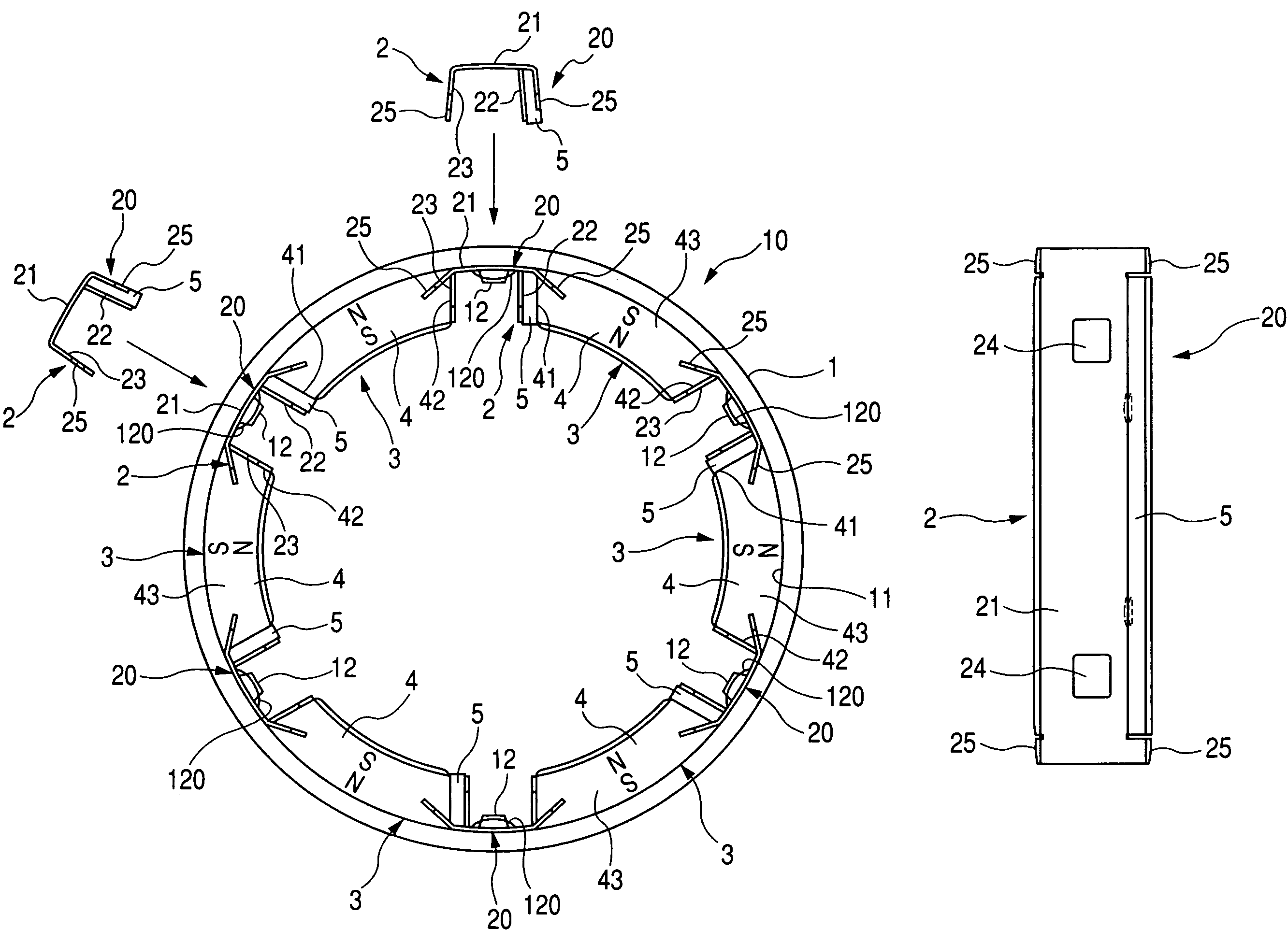
Yoke assembly for stator of starter motor
a starter motor and stator technology, applied in the direction of dynamo-electric machines, electrical apparatus, magnetic circuit shapes/forms/construction, etc., can solve the problems of difficulty in achieving a reduction in manufacturing costs on mass production, and achieve the effect of smooth assembly, less leakage of magnetic fluxes, and improved output performan
- Summary
- Abstract
- Description
- Claims
- Application Information
AI Technical Summary
Benefits of technology
Problems solved by technology
Method used
Image
Examples
first embodiment
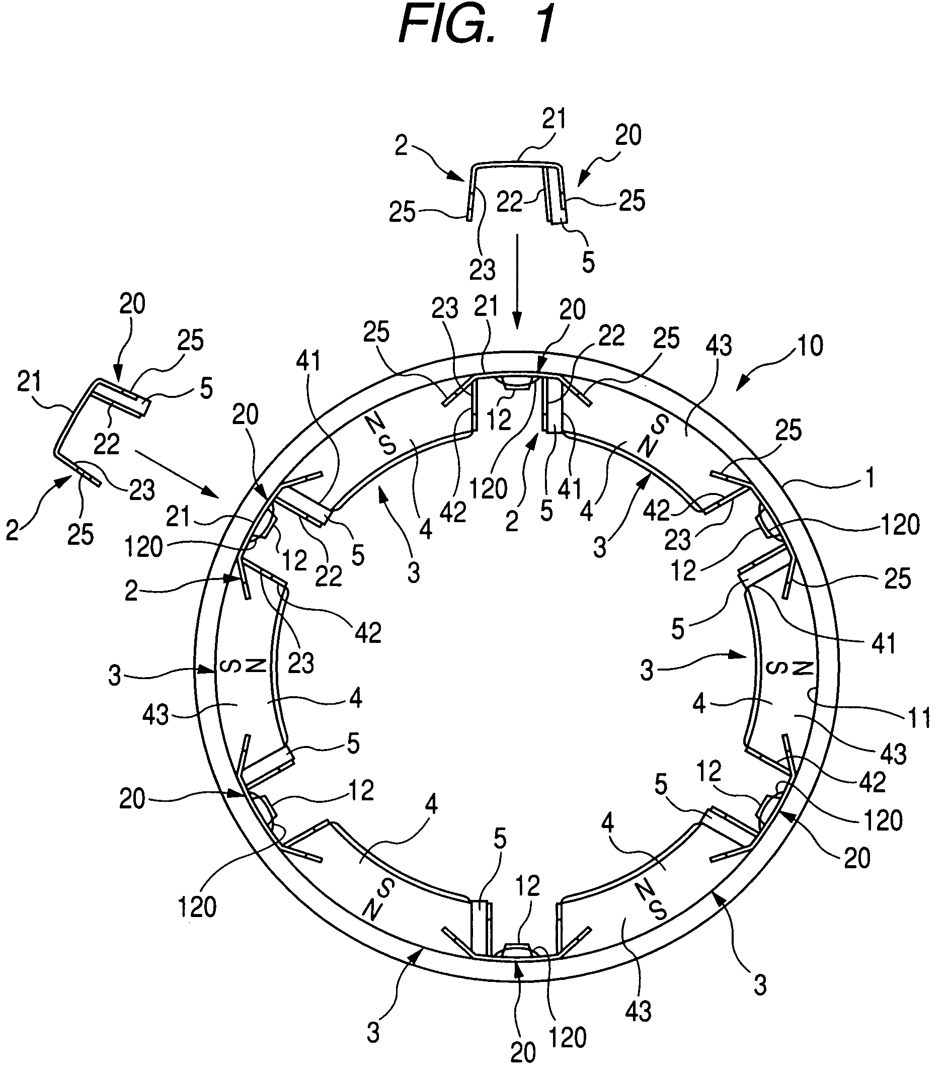
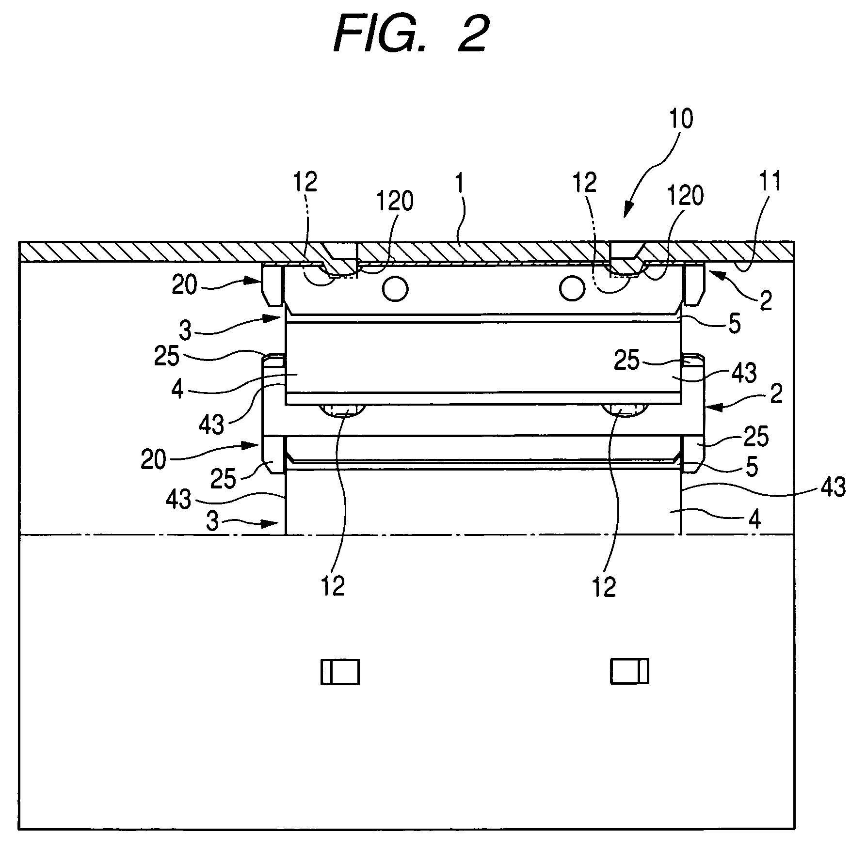
[0038]A yoke assembly of one embodiment according to the present invention for use in a stator of a starter motor mounted on an automotive engine is described below with reference to FIGS. 1 and 2.
[0039]As shown in FIGS. 1 and 2, the yoke assembly 10 includes a cylindrical yoke 1 having an inner circumferential periphery 11, a plurality of magnet springs 2 fixedly secured to the inner circumferential periphery 11 of the cylindrical yoke 7 at equidistantly spaced intervals along a circumferential direction of the inner circumferential periphery 11, and a plurality of stator elements 3 retained with the magnet springs 2, respectively. A fundamental structure of the starter motor to which the yoke assembly 10 is applied is well known in the art and an armature, having a rotary shaft (not shown), is coaxially accommodated in the yoke 1.
[0040]With the present embodiment, the inner peripheral wall 11 of the yoke 1 carries thereon six magnet springs 2, fixedly secured at circumferentially ...
second embodiment
[0048]A yoke assembly of a second embodiment according to the present invention will be described below in detail with reference to FIGS. 6 to 8.
[0049]FIG. 6 shows the yoke assembly 10A of the present embodiment. With the present embodiment, the yoke assembly 10A takes the form of a structure including stator elements 3A each of which includes a main pole 4 and an auxiliary pole 5, placed in direct contact with a magnet spring 2A and each of which has a pole-to-pole magnet 6 placed inside the magnet spring 2A.
[0050]As shown in FIGS. 7 to 7C, each magnet spring 2 has an interior, formed in a mounting chamber 60 for the pole-to-pole magnet 6, and has both side plates 22 and 23. The side plates 22 and 23 have radially inward areas, closer to the center of the yoke assembly 10A, which are formed with ledge segments 2a and 2a circumferentially extending inward from the side plates 22 and 23. The ledge segments 2a and 2a serve as holder sections for holding each pole-to-pole magnet 6 to c...
PUM
 Abstract
Description
Claims
Application Information
 - R&D
- Intellectual Property
- Life Sciences
- Materials
- Tech Scout
- Unparalleled Data Quality
- Higher Quality Content
- 60% Fewer Hallucinations
Browse by: Latest US Patents, China's latest patents, Technical Efficacy Thesaurus, Application Domain, Technology Topic, Popular Technical Reports.
© 2025 PatSnap. All rights reserved.Legal|Privacy policy|Modern Slavery Act Transparency Statement|Sitemap|About US| Contact US: help@patsnap.com


