
Cable telephony network supporting roaming VoIP terminals

a terminal and cable telephony technology, applied in the field of communication systems, can solve the problems of destroying in part the low cost attractiveness of voip telephony, affecting the quality of voip telephony to be significantly worse than that of pstn telephony, and the latency of packet data transmission between the internet and other services of packet data networks

Inactive Publication Date: 2009-08-04
AVAGO TECH INT SALES PTE LTD
View PDF4 Cites 8 Cited by
  • Summary
  • Abstract
  • Description
  • Claims
  • Application Information

AI Technical Summary

Benefits of technology

The present invention is about a device and methods for using it. The details of the invention can be found in the accompanying drawings and description. The technical effects of the invention will be explained in more detail in the following description.

Problems solved by technology

When VoIP telephony was first introduced, the data packet transmission latency of the Internet and of other servicing networks caused the quality of VoIP telephony to be significantly worse than that of PSTN telephony.
Over time, packet data transmission latency of the Internet and of other servicing packet data networks has decreased.
However, only a limited number of people have a computer upon which this VoIP telephony application may be loaded and have Internet access of a quality that will support the VoIP telephony application.
VoIP telephony service providers typically extract a toll for servicing a call via the VoIP gateway bridge, thus destroying in part the low cost attractiveness of VoIP telephony.
However, difficulties exist with such systems due to the non-local PSTN access of telephones, e.g., 911 call servicing, that make these systems unattractive from other standpoints.

Method used


Image

  • Cable telephony network supporting roaming VoIP terminals
  • Cable telephony network supporting roaming VoIP terminals
  • Cable telephony network supporting roaming VoIP terminals

Examples


Embodiment Construction

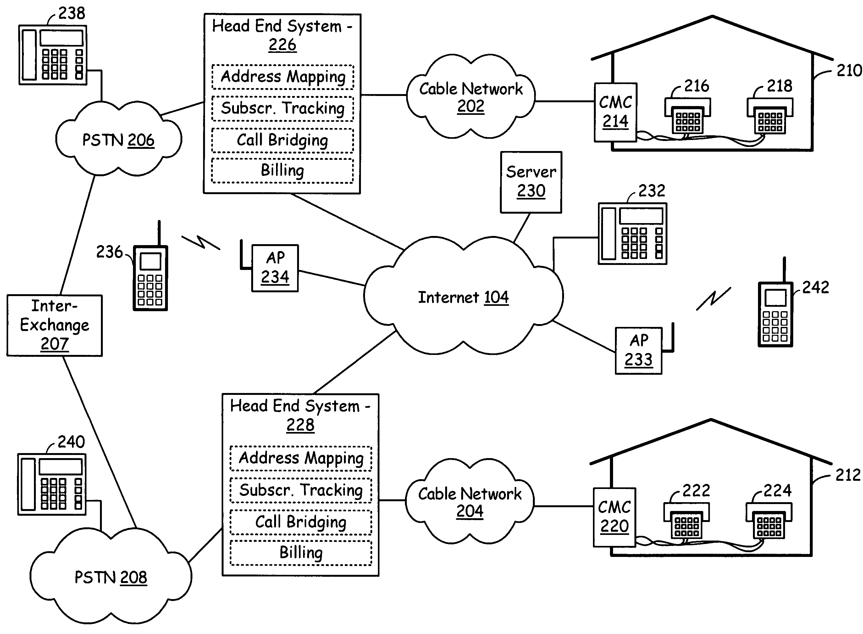
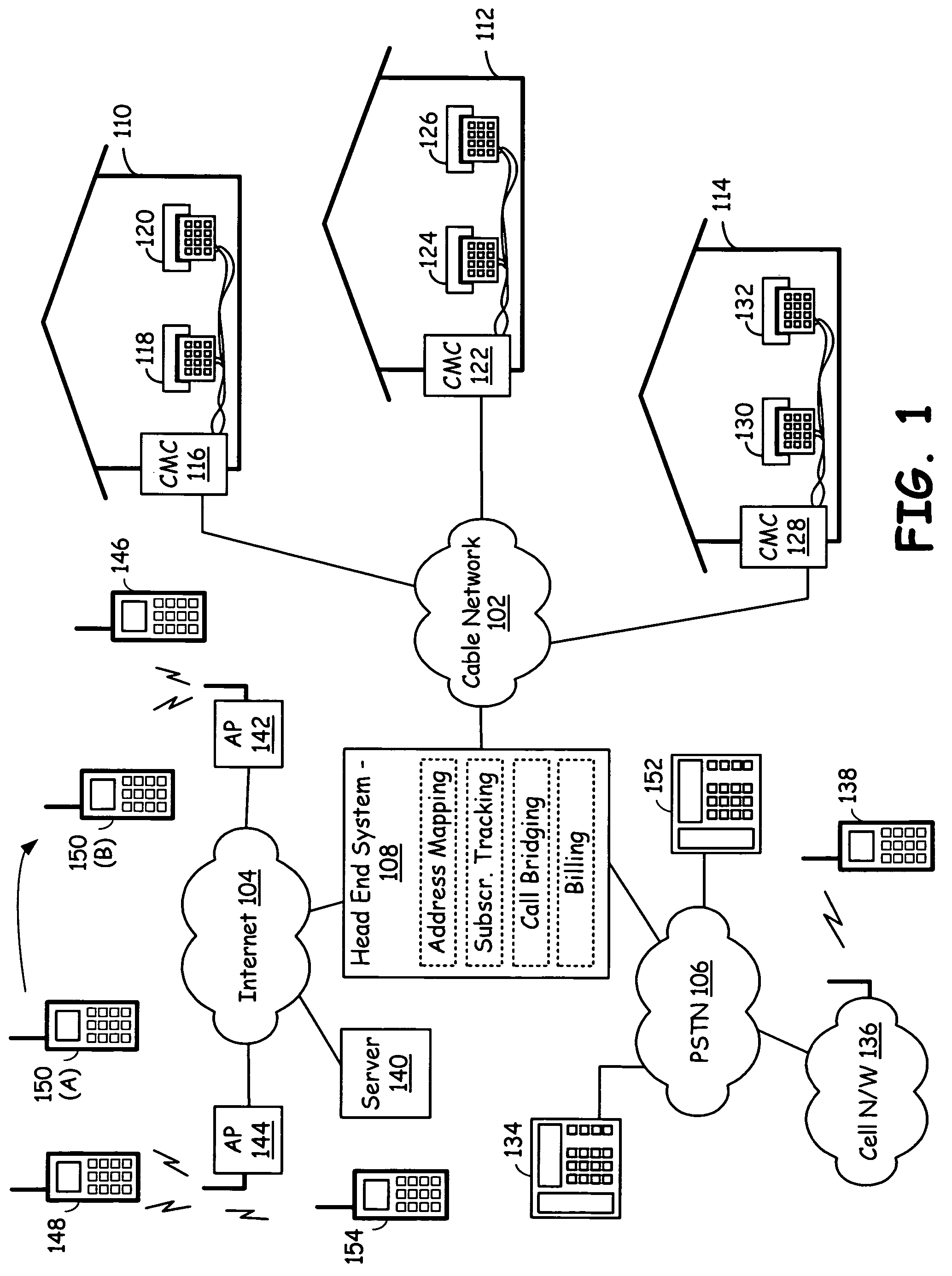
[0023]FIG. 1 is a system diagram illustrating a cable infrastructure constructed according to an embodiment of the present invention. The cable infrastructure of FIG. 1 is formed and operates in conjunction with a communication infrastructure that includes the Public Switched Telephony Network (PSTN) 106 and the Internet 104. As generally known, the PSTN supports PSTN telephony while the Internet supports Voice over Internet Protocol (VoIP) telephony. The cable infrastructure services a plurality of subscribers and includes a cable network 102, a plurality of cable modem circuits 116, 122, and 128, a plurality of telephones 118, 120, 124, 126, 130, and 132, and a head end system 108. Each of the plurality of telephones 118, 120, 124, 126, 130, and 132 may be a Plain Old Telephone System (POTS) telephone and support a POTS interface. However, with other embodiments of the present invention, these telephones 118, 120, 124, 126, 130, and 132 support a digital interface or another type ...


PUM


Abstract

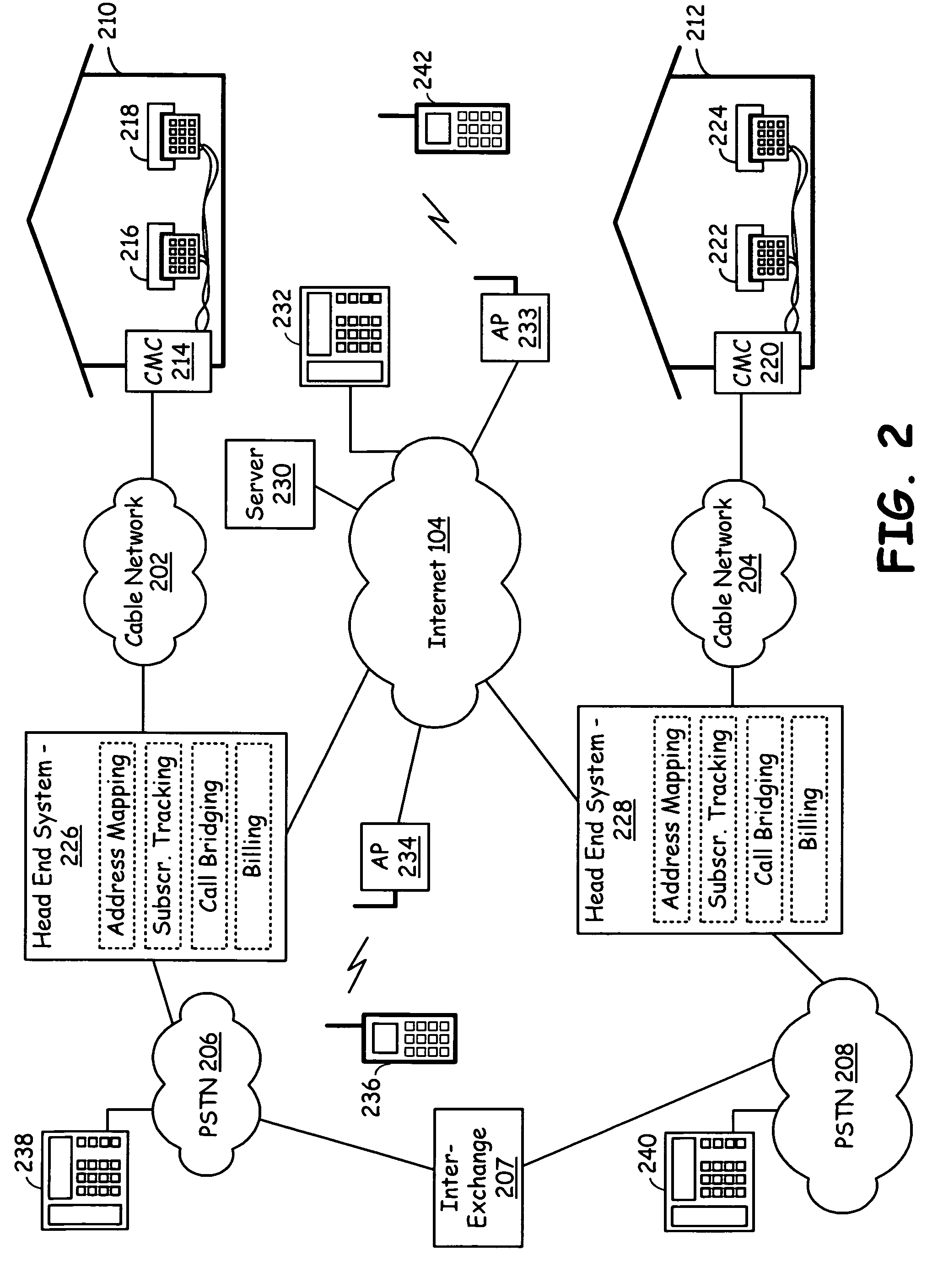
A cable infrastructure includes a plurality of cable modem circuits communicatively coupled to a cable network and associated with a corresponding one of a plurality of subscribers. Each of a plurality of telephones has both a POTS (Plain Old Telephone System) interface and a unique telephone number and associates with a corresponding one of the plurality of subscribers. Each of a plurality of interface circuits couples one of the plurality of cable modem circuits with a corresponding one of the plurality of telephones via the POTS interface. A head end system communicatively couples to the cable network, the public switched telephony network, and the Internet network and supports address mapping that enables communication exchanges between one of the plurality of telephones and an Internet telephony device. The address mapping also enables communication exchanges between telephones serviced by differing head ends via an Internet pathway that is independent of the public switched telephony network.

Description

CROSS REFERENCES TO RELATED APPLICATIONS[0001]This application is a continuation-in-part of the following co-pending applications:[0002]1. Utility application Ser. No. 11 / 348,962, filed on Feb. 7, 2006, and entitled “TELEPHONE SUPPORTING BRIDGING BETWEEN A PACKET SWITCHED NETWORK AND THE PUBLIC SWITCHED TELEPHONE NETWORK”;[0003]2. Utility application Ser. No. 11 / 348,814, filed on Feb. 7, 2006, and entitled “COMPUTING DEVICE SUPPORTING BRIDGING BETWEEN A PACKET SWITCHED NETWORK AND THE PUBLIC SWITCHED TELEPHONE NETWORK”;[0004]3. Utility application Ser. No. 11 / 348,743, filed on Feb. 7, 2006, and entitled “SET TOP BOX SUPPORTING BRIDGING BETWEEN A PACKET SWITCHED NETWORK AND THE PUBLIC SWITCHED TELEPHONE NETWORK”; and[0005]4. Utility application Ser. No. 11 / 386,586, filed on Mar. 22, 2006, and entitled “SERVICE EXCHANGE IN A VOIP TO TELEPHONY BRIDGING NETWORK”, all of which are incorporated herein in their entirety for all purposes.BACKGROUND OF THE INVENTION[0006]1. Technical Field o...

Claims


Application Information

Patent Timeline
Patent Type & Authority Patents(United States)
IPC IPC(8): H04L12/66
CPCH04L12/6418H04L29/06027H04M1/2535H04L65/1036H04M7/1225H04L65/1069H04L65/1026H04M7/1205H04L65/1095H04L65/1101
Inventor BENNETT, JAMES D.
Owner AVAGO TECH INT SALES PTE LTD
Learn More