Safety and rescue carabiner holder

a carabiner and safety technology, applied in the field of safety and rescue operations, can solve the problems of inability to extract workers, inability to work, and inability to work independently, and the current state of the art for carabiner holders does not meet the needs of the safety and rescue sector

Inactive Publication Date: 2009-08-11
QUASAR SERVICES
View PDF12 Cites 13 Cited by
  • Summary
  • Abstract
  • Description
  • Claims
  • Application Information

AI Technical Summary

Benefits of technology

[0012]The safety and rescue carabiner holder of the present invention is a device that overcomes the deficiencies of existing carabiner holders originally designed for recreational climbing purposes. When attached to an extension pole, it is capable of securely holding a carabiner with its gate arm in the open position while extending the user's reach several feet in any direction, all the while supporting a long and heavy segment of attached safety rope, or even the weight of a small block and tackle. The spring-loaded grip of the carabiner holder is firm enough to withstand shaking and bouncing, but will release easily after attachment by pulling the extension pole firmly backwards.
[0014]The projecting foot on the L-bracket includes a groove in its upper surface that grasps the rounded bottom of the carabiner and prevents it from twisting out of position, despite a shifting load vector created by the weight of the freely hanging safety rope. The clamping grip generated of the set of jaw arms ensures that once the carabiner is properly positioned in the holder, it will stay in place until the carabiner is hooked into a target ring and the user tugs on the extension pole. The carabiner holder may be made with solid metal components, such as aluminum, in order to withstand the rigors and abuse of an industrial work environment.

Problems solved by technology

Regrettably, unforeseen circumstances sometimes occur or mistakes are made which render a worker incapacitated and unable to extract him / herself from a dangerous situation, and where it would be equally hazardous for rescue team members to enter and attempt to retrieve the fallen individual in person.
Unfortunately, the current state of the art for carabiner holders does not satisfy the needs of the safety and rescue sector.
But it is especially critical when the fallen worker lies downward and away from the rescuer's location, such as in a trench, down a sewer manhole, in a ventilation shaft, or lower on the face of a structure.
Furthermore, a rescuer is likely to be nervous or agitated during an emergency and may be unable to hold the extension pole completely steady.
If the rescuer does bounce the extension pole while attempting to attach the carabiner, these shocks will increase the probability that the carabiner will fall out of the holder before it can be attached to the harness.
The carabiner holders presently available have been adapted from the climbing industry and are not sufficiently strong or robust enough to provide reliable operation in an emergency situation.
If the carabiner holder is extended too far to one side or the other, however, the weight of the rope tends to pull the carabiner out of position and causes either the carabiner's gate arm to prematurely release and snap shut, or the carabiner to fall out of the holder altogether.
However, such unreliable operation in an emergency situation could prove fatal to the fallen party.
Several existing designs are also complicated to operate, as they require special manipulation of the holder when connecting the carabiner to a D-ring or hanger, or they call for twisting or pushing the extension pole to one side to release the carabiner from the holder after it has been attached to the safety harness.
Such procedures may be forgotten or overlooked by a would-be rescuer in the heat of the moment, slowing down or hindering the speed of the rescue operation.
The device must also be simple to use, as rescuers can often be nervous or agitated when time constraints dictate that a fallen coworker or friend be retrieved as soon as possible.
And most importantly, the holder must provide reliable operation in any orientation, and not allow the carabiner's gate arm to release inadvertently or the carabiner to fall out of the holder prematurely if the individual to be rescued is located in an awkward position.

Method used


Image

  • Safety and rescue carabiner holder
  • Safety and rescue carabiner holder
  • Safety and rescue carabiner holder

Examples


Embodiment Construction

[0021]Reference will now be made to the exemplary embodiment illustrated in the drawings, and specific language will be used herein to describe the same. It will nevertheless be understood that no limitation of the scope of the invention is thereby intended. Alterations and further modifications of the inventive features illustrated herein, and additional applications of the principles of the invention as illustrated herein, which would occur to one skilled in the relevant art and having possession of this disclosure, are to be considered within the scope of the invention.

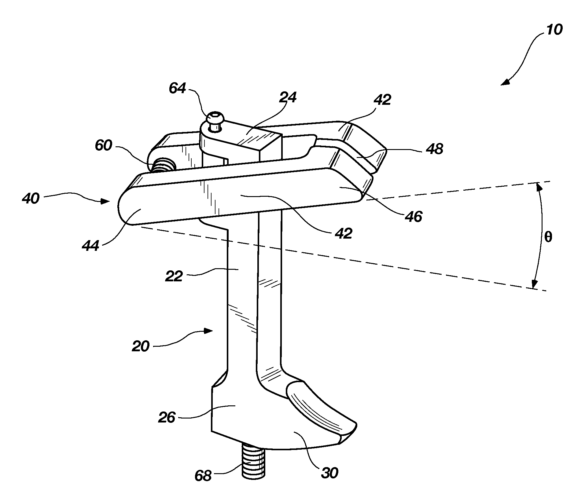
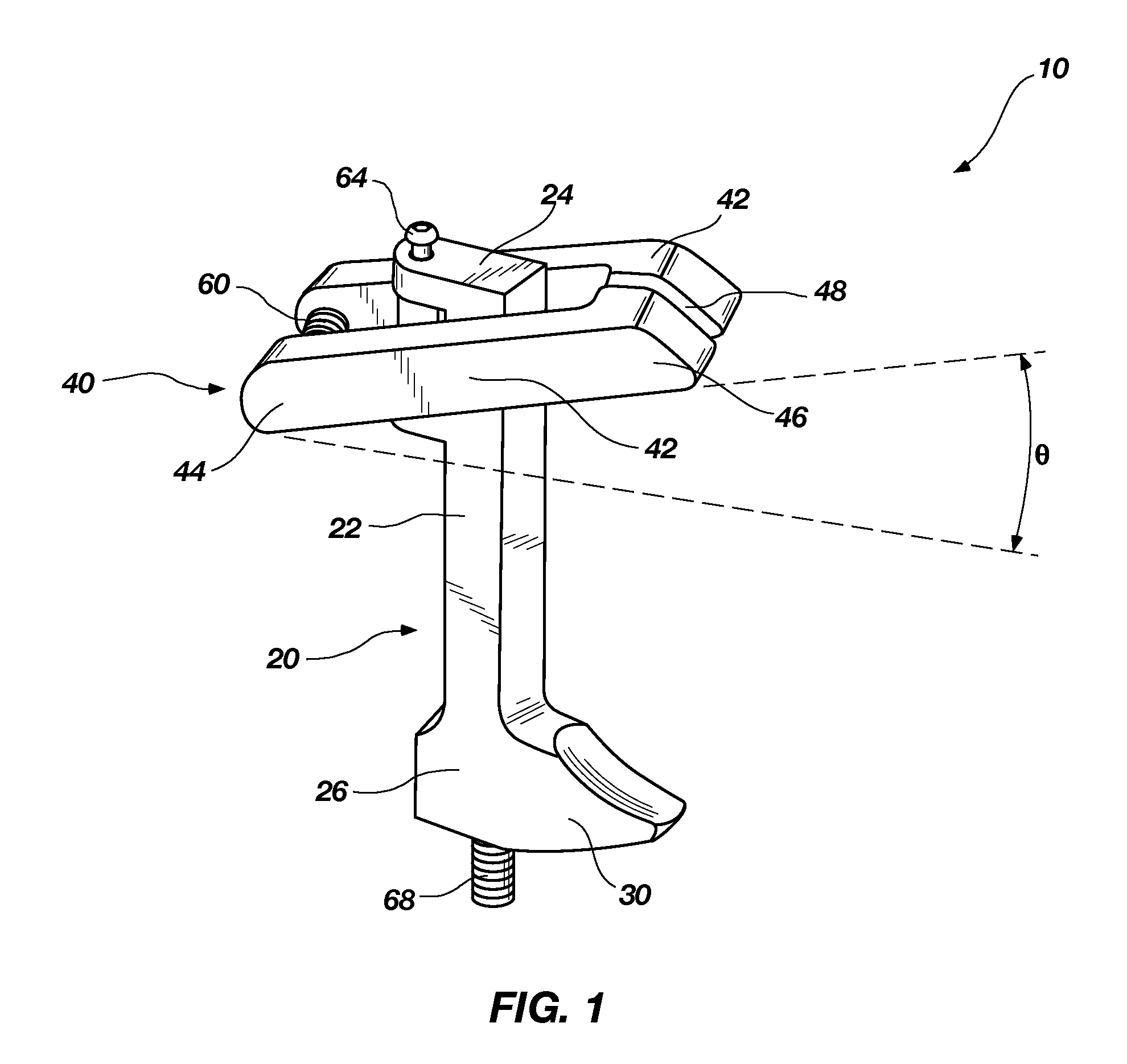
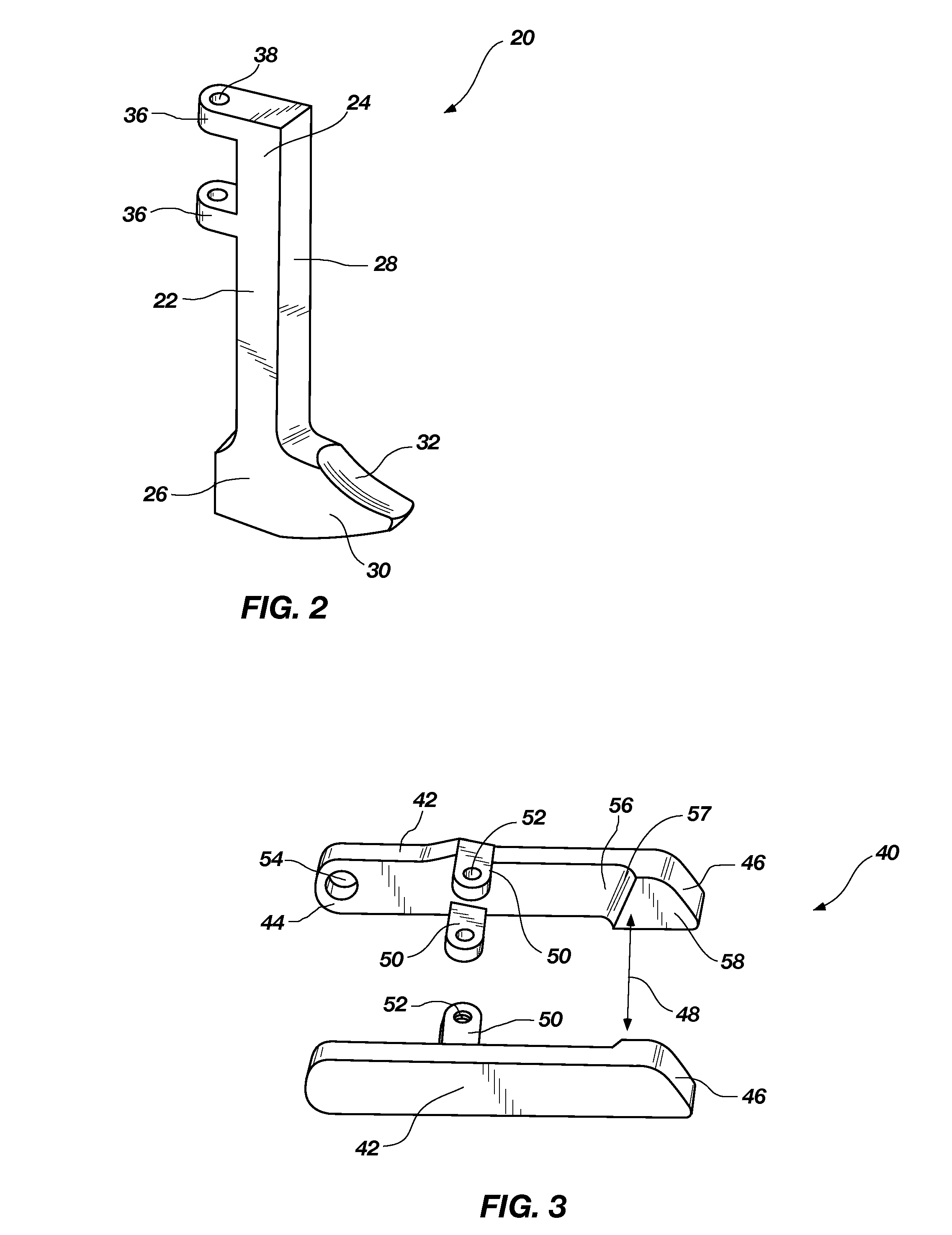
[0022]FIG. 1 illustrates a safety and rescue carabiner holder 10 according to a preferred embodiment of the present invention. The carabiner holder is comprised of two principle components: an L-bracket 20, and a gripping structure 40. The L-bracket is justly named as it has a long axial stem 22 with an upper end 24 and a lower end 26, and a projecting foot 30 which extends from its lower end. The configuration of ...


PUM


Abstract

A safety and rescue carabiner holder for securing a carabiner with its gate in the open position while extending the user's reach several feet in any direction, which is also capable of supporting a long and heavy segment of attached safety rope. The carabiner holder is mounted to the end of an extension pole and includes a restraining structure that grips the bottom of the carabiner and a set of spring-loaded jaw arms that firmly clamp the spine and gate arm of the carabiner in a manner strong enough to withstand any inadvertent shaking and bouncing, ensuring that the carabiner will stay in place until hooked into a target ring and the user releases the carabiner by pulling backwards on the extension pole.

Description

RELATED APPLICATIONS[0001]This application claims priority to U.S. Provisional Application Ser. No. 60 / 831,719, filed Jul. 17, 2006, which is incorporated by reference in its entirety herein.FIELD OF THE INVENTION[0002]The field of the invention relates to safety and rescue operations and, more specifically, to the installation of a carabiner with its attached safety rope to the D-ring on the harness of a fallen or otherwise incapacitated worker.BACKGROUND OF THE INVENTION AND RELATED ART[0003]It is common for workers employed in the construction and maintenance aspects of any heavy industry to enter into hazardous situations during their normal scope of employment. Examples of such activities include digging trenches for pipelines, entering confined spaces such as sewers or large storage tanks, and climbing on the exteriors of tall structures such as buildings, process columns, exhaust flumes or power line towers. Great efforts have been expended through the implementation of OSHA ...

Claims


Application Information

Patent Timeline
Patent Type & Authority Patents(United States)
IPC IPC(8): B25J1/04A62B99/00
CPCA63B29/02A62B99/00Y10S248/925
Inventor MORTENSEN, STEPHEN
Owner QUASAR SERVICES
Why Eureka
Try Eureka