Miniature cross stream thrombectomy catheter

a thrombus and catheter technology, applied in the field of thrombus catheters, can solve the problems of affecting the thin vessel wall of the thin vessel, the bulky profile of the thrombus device, and the inability to accommodate all vascular regions, so as to increase the ablation action, increase the velocity, and increase the effect of particle evacuation

Inactive Publication Date: 2009-08-11
BOSTON SCI LTD
View PDF124 Cites 12 Cited by
  • Summary
  • Abstract
  • Description
  • Claims
  • Application Information

AI Technical Summary

Benefits of technology

[0009]Another significant aspect and feature of the present invention is a miniature cross stream thrombectomy catheter which minimizes vessel damage by the use of a nominal fluid jet flow velocity.
[0012]A further significant aspect and feature of the present invention is a miniature cross stream thrombectomy catheter as found in alternative embodiments which includes the use of an insert to create increased velocity fluid jet flow of greater than nominal jet flow for increased ablation action and increased particle evacuation.
[0013]A still further significant aspect and feature of the present invention is a miniature cross stream thrombectomy catheter having multiple annulus structure where one annulus structure provides for thrombus ablation at a nominal rate and where another annulus structure provides for increased evacuation of thrombotic particles.

Problems solved by technology

Often, thrombectomy devices, due to the complexity and multiple component structure, exhibited a profile of a bulky nature which could not be accommodated by all vascular regions, such as vessels extending into the brain, which are of smaller size than vessels found in other regions of the body.
Excess ablation fluid medium velocity can be detrimental to the thin vessel walls, such as those found in the brain, where damage, such as vessel wall perforation, could occur.
Other difficulties encountered with prior art thrombectomy catheters are related to the fashioning thereof where producing small components is difficult to accomplish and, as such, can prove expensive to manufacture.
Especially difficult to produce is an emanator loop with rearwardly facing jet orifices and other like components which are located at the distal portion of some prior art thrombectomy catheters.

Method used


Image

  • Miniature cross stream thrombectomy catheter
  • Miniature cross stream thrombectomy catheter
  • Miniature cross stream thrombectomy catheter

Examples


Embodiment Construction

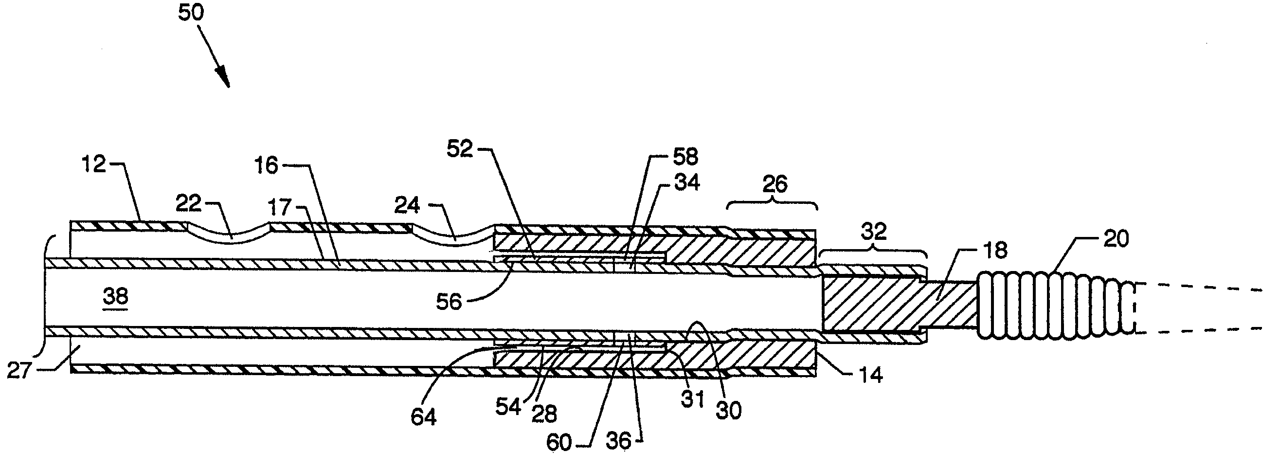
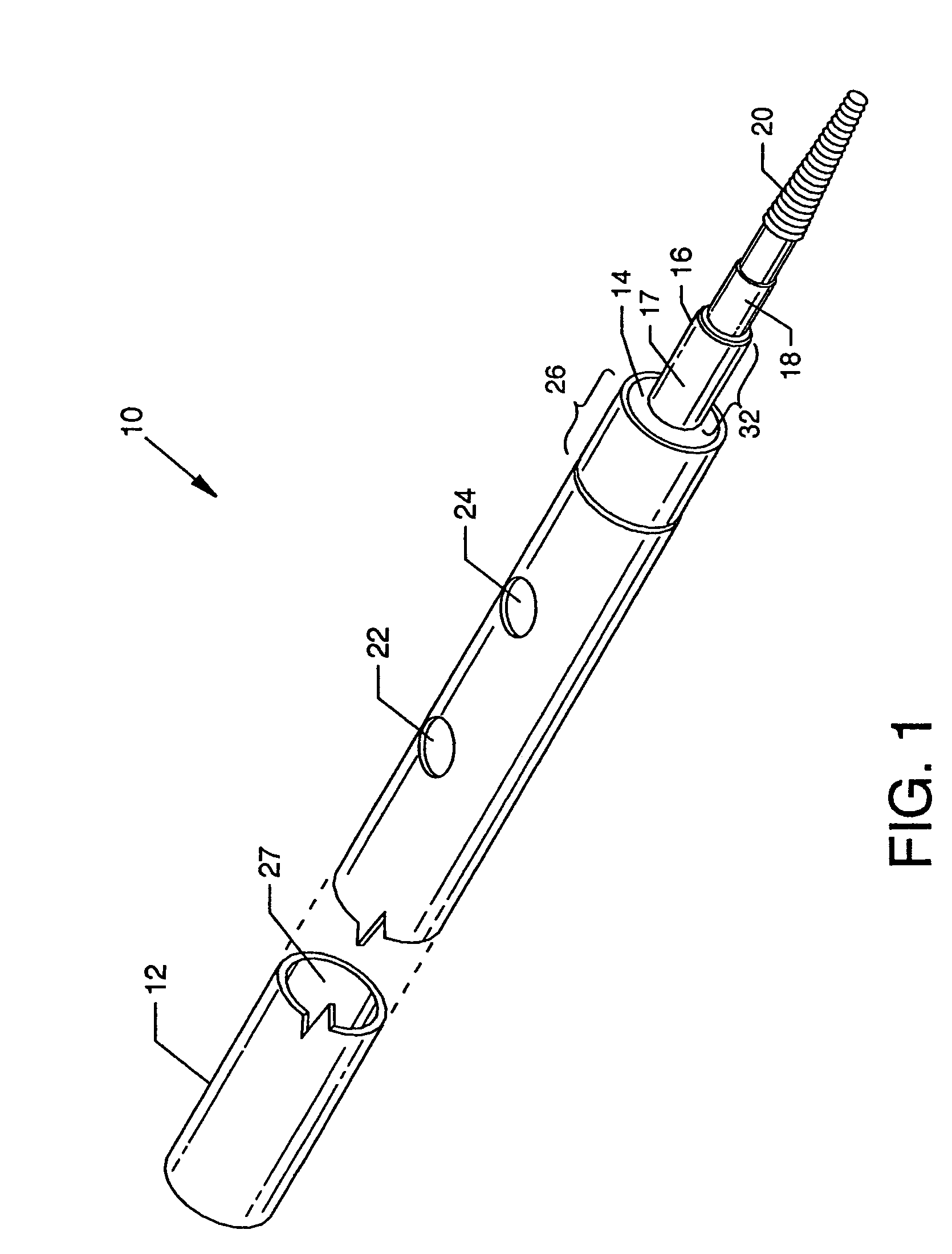
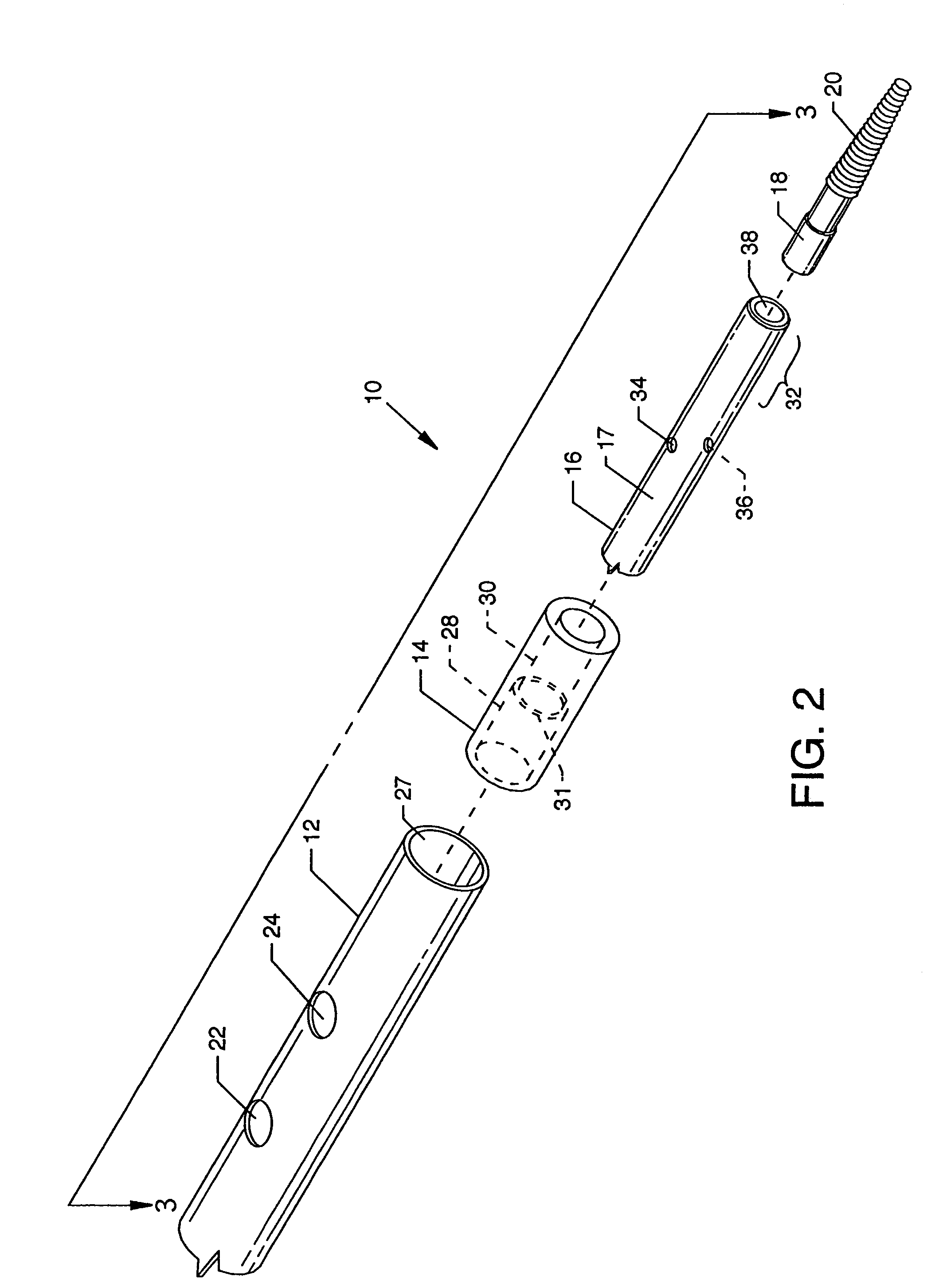
[0035]FIG. 1 is a foreshortened isometric view of a miniature cross stream thrombectomy catheter 9, a first embodiment of the present invention. Readily discernable major and other components visible in the illustration include a flexible exhaust tube 12 preferably of a suitable and flexible plastic or other material, a flow director 14 preferably concentrically aligned within a distal portion of the exhaust tube 12, a hypo-tube 16 aligned preferably concentrically to and extending a short distance in a distal direction beyond the distal ends of the flow director 14 and the exhaust tube 12, a plug 18, a crimp 26 at the distal end of the exhaust tube 12, and a flexible tip 20 secured about and extending from the plug 18. Also visible is an outflow orifice 22 and an inflow orifice 24 extending through the distal region of the exhaust tube 12. More than one outflow orifice 22 and more than one inflow orifice 24 can be utilized as required. The distally located crimp 26 visible at the d...


PUM

PropertyMeasurementUnit
pressureaaaaaaaaaa
velocityaaaaaaaaaa
flexibleaaaaaaaaaa

Abstract

A miniature cross stream thrombectomy catheter useful in small blood vessel thrombectomy procedures. An annulus near the distal end of the miniature cross stream thrombectomy catheter is formed between a hypo-tube and a proximally directed bore of a concentrically aligned flow director whereby jet orifices in the hypo-tube communicate with the annulus to direct jet flows of saline or other fluid around and about the annulus and to be directed proximally from the annulus to pass through one or more outflow orifices and thence to pass through one or more inflow orifices thereby creating an ablation flow therebetween which loosens and carries away thrombotic materials from the walls of a blood vessel.

Description

CROSS REFERENCES TO RELATED APPLICATIONS[0001]None.BACKGROUND OF THE INVENTION[0002]1. Field of the Invention[0003]The present invention is for a thrombectomy catheter, and more particularly, relates to a miniature cross stream thrombectomy catheter.[0004]2. Description of the Prior Art[0005]Prior art thrombectomy catheters, while being effective in many uses and situations, were fashioned of complex geometrical component configurations involving multiple components to ablate thrombus and other materials in the vasculature. Often, thrombectomy devices, due to the complexity and multiple component structure, exhibited a profile of a bulky nature which could not be accommodated by all vascular regions, such as vessels extending into the brain, which are of smaller size than vessels found in other regions of the body. Also, vessels in the brain, being of smaller proportion, have vessel walls which are thinner and more delicate than the walls of larger vessels and, therefore, require gr...

Claims


Application Information

Patent Timeline
Patent Type & Authority Patents(United States)
IPC IPC(8): A61M1/00
CPCA61B17/22A61B17/32037Y10T29/49826A61B2017/22084
Inventor WEISEL, STEPHEN E.BONNETTE, MICHAEL J.LE, HIEU V.KOZAK, DEBRA M.
Owner BOSTON SCI LTD
Why Eureka
Try Eureka