Prismatic battery made of multiple individual cells

a technology of individual cells and batteries, applied in the field of individual cell batteries, can solve the problems of uneven cell voltage, large limitation of battery use, and substantially faster aging of the warmer cells in the center of the module, and achieve the effect of reducing the number of cells

Inactive Publication Date: 2009-08-11
DAIMLER AG
View PDF5 Cites 33 Cited by
  • Summary
  • Abstract
  • Description
  • Claims
  • Application Information

AI Technical Summary

Benefits of technology

[0015]An object of the present invention is to improve a prismatic battery in such a way that a simple, compact, and cost-effective battery structure is made possible.
[0016]The present invention provides a prismatic battery with a cooling member for a stack of prismatic modules, which are connected under tension in the direction of the stack via end plates and tension members to form the battery. The cooling fins of the cooling member according to the present invention run parallel to the direction of this tensioning pull. The heat thus flows from the individual electrochemical cells toward the cooling fins of the cooling member largely perpendicularly to the direction of tensioning pull. An expansion of the individual modules due to pressures produced therein thus has no effect on the contact between the individual modules and the cooling fins, since the latter are situated along the primary direction of module expansion. Furthermore, this allows the module stack to slide in the direction of the end plates as a result of a change in gas pressure within the modules, without the contact between the cooling fins or the cooling capacity being impaired thereby.
[0017]This provides the battery according to the present invention with a particularly simple and compact design having efficient cooling, so that it is especially suitable, for example, for the preferred application as a traction battery in a vehicle.
[0019]This achieves even and efficient cooling of the individual module cells by the cooling member, regardless of their position in the module, and of the individual modules, regardless of their position in the stack. In particular, if the slots are situated between the individual cells, and the cooling fins are provided in the slots, the electrode stack present in each electrochemical cell is able to be evenly cooled along the highly conductive metallic electrode films over the entire height of the electrode stack, since heat does not have to flow in the direction of the stack, but rather the heat may be removed perpendicularly to the individual electrode films on the cooling fins. In a construction of this type, both the individual electrochemical cells in the modules and the modules themselves are already fixed in place by the cooling fins in a horizontal direction transverse to the stack tensioning and may be protected by the cooling member against mechanical damage, for example from their bottoms or, if multiple cooling members are used which engage with the modules from above and below, from both sides.

Problems solved by technology

The uneven cooling of the individual electrochemical cells in the module then results in uneven cell voltages during module operation and in a substantially faster aging of the warmer cells in the center of the module.
The use of the battery, for example in a vehicle, can therefore be limited to a great extent by an aging-related loss in the capacitance of a single cell.
The best way to counteract this effect requires highly complex and, in particular, large cooling devices, which are difficult to accommodate in motor vehicles, especially in the small amount of space available.
Furthermore, the use of air as a cooling medium, for example in the aforementioned EP publication, has the disadvantage that high-volume air channels, air filters, and fans are needed to conduct the quantity of air needed for cooling.
It is further problematic to implement an air cooling system, since the input temperature of the air used should not be excessively high for effective cooling.
For example, battery cooling is not as efficient at extremely high ambient temperatures as it is at much lower ambient temperatures.
A problem with the design according to the aforementioned US publication is that uniform mechanical joining of the stack of modules under tension is no longer possible, due to the rigid cooling fins.
When gas pressure builds up in the individual cells, the outer housing walls of the modules therefore begin to bulge.
As a result, air gaps, which result in loss of thermal contact between the module and cooling fins, form between the module and cooling fin, due to the module deformation caused by the pressure rising therein.
This means that uniform cooling can also not be ensured.
Once again, this results in the aforementioned disadvantages of poor and, in particular, uneven cooling of the individual module cells.
However, it has the disadvantage that achieving sufficient stability in a material structure of this type having integrated metal plates requires very thick materials.
However, these very thick materials, which are typically made of plastic material forming the casing of the metal plates, have the disadvantage that they are poor heat conductors.
Furthermore, in the case of the integrated metal plates according to the aforementioned EP publication, the thermal coupling of the metal plates to the cooled base plate is extremely difficult.
This function alone, which is necessary as a result of the unavoidable, pressure-related expansion in the battery stack, makes it clear that maintaining clean and uninterruptible conduction of heat from the integrated metal plates to the base plate for all phases of operation will be very difficult.
A further disadvantage is certainly the fact that constructing the modules from different materials having varying coefficients of thermal expansion is critical.
Even this construction therefore results in air gaps which substantially impair thermal conductivity and also significantly reduce the mechanical stability of such modules, which is important due to the pressure fluctuations.

Method used


Image

  • Prismatic battery made of multiple individual cells
  • Prismatic battery made of multiple individual cells
  • Prismatic battery made of multiple individual cells

Examples


Embodiment Construction

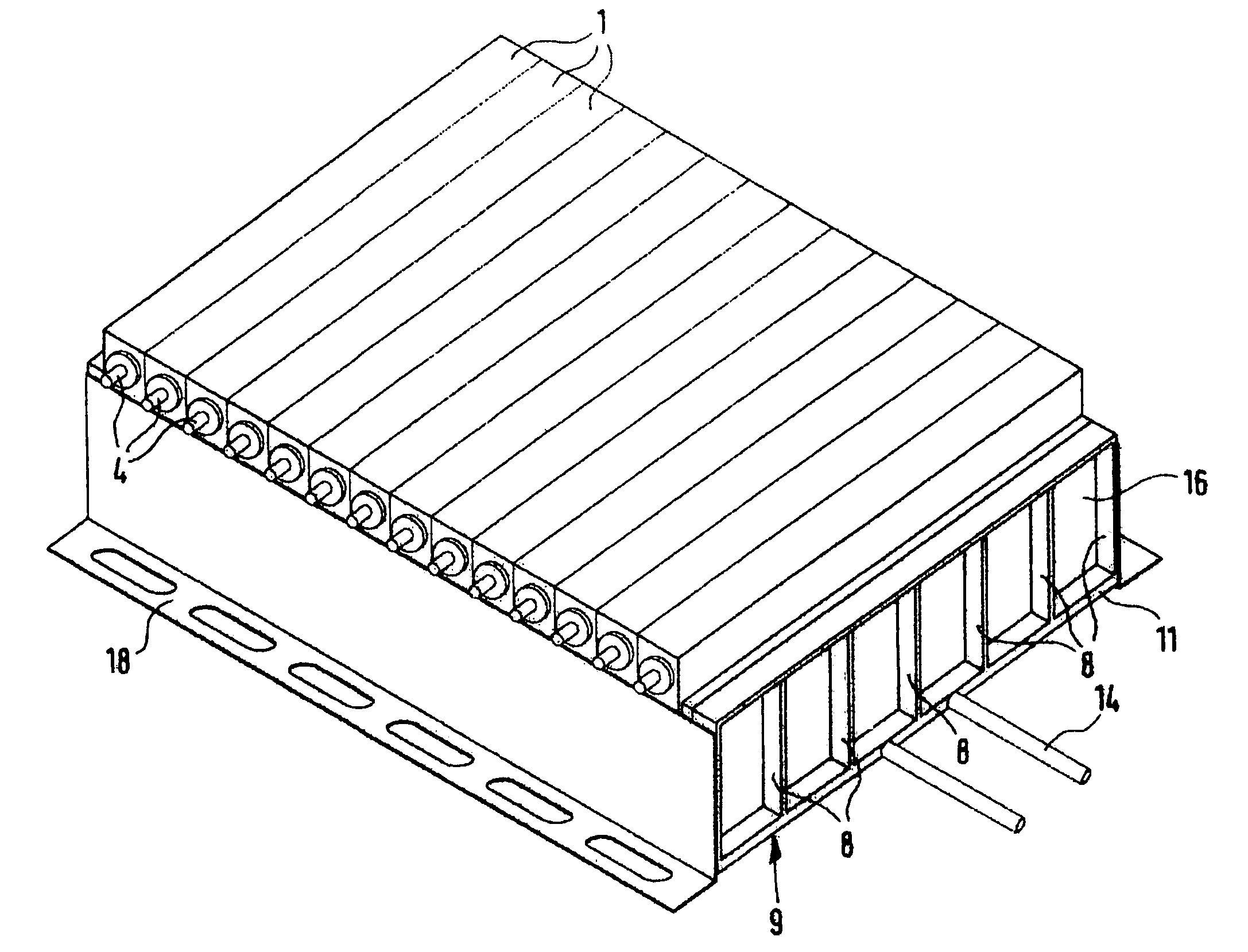
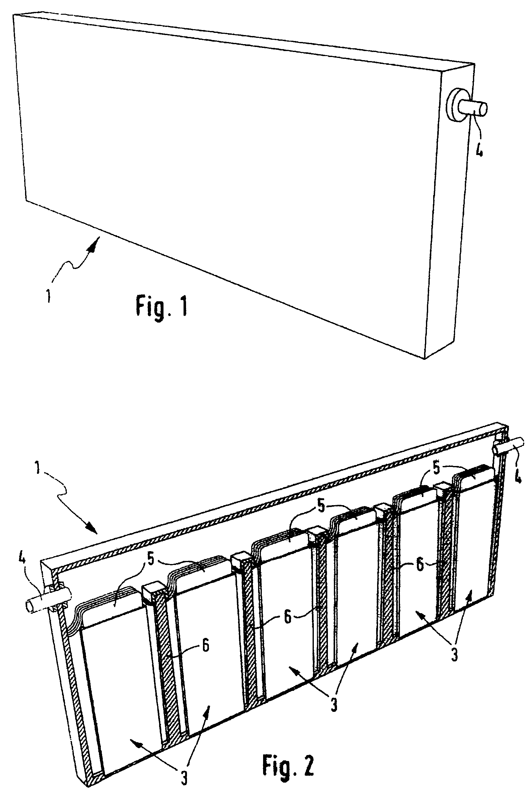
[0030]FIG. 1 shows a single module 1 of a battery 2, which is illustrated in its entirety later on. This module 1 is typically made up of multiple individual electrochemical cells 3, which are situated inside module 1 and are not visible in the representation selected here. Module 1 also includes two electric connections 4, one of which is illustrated here.

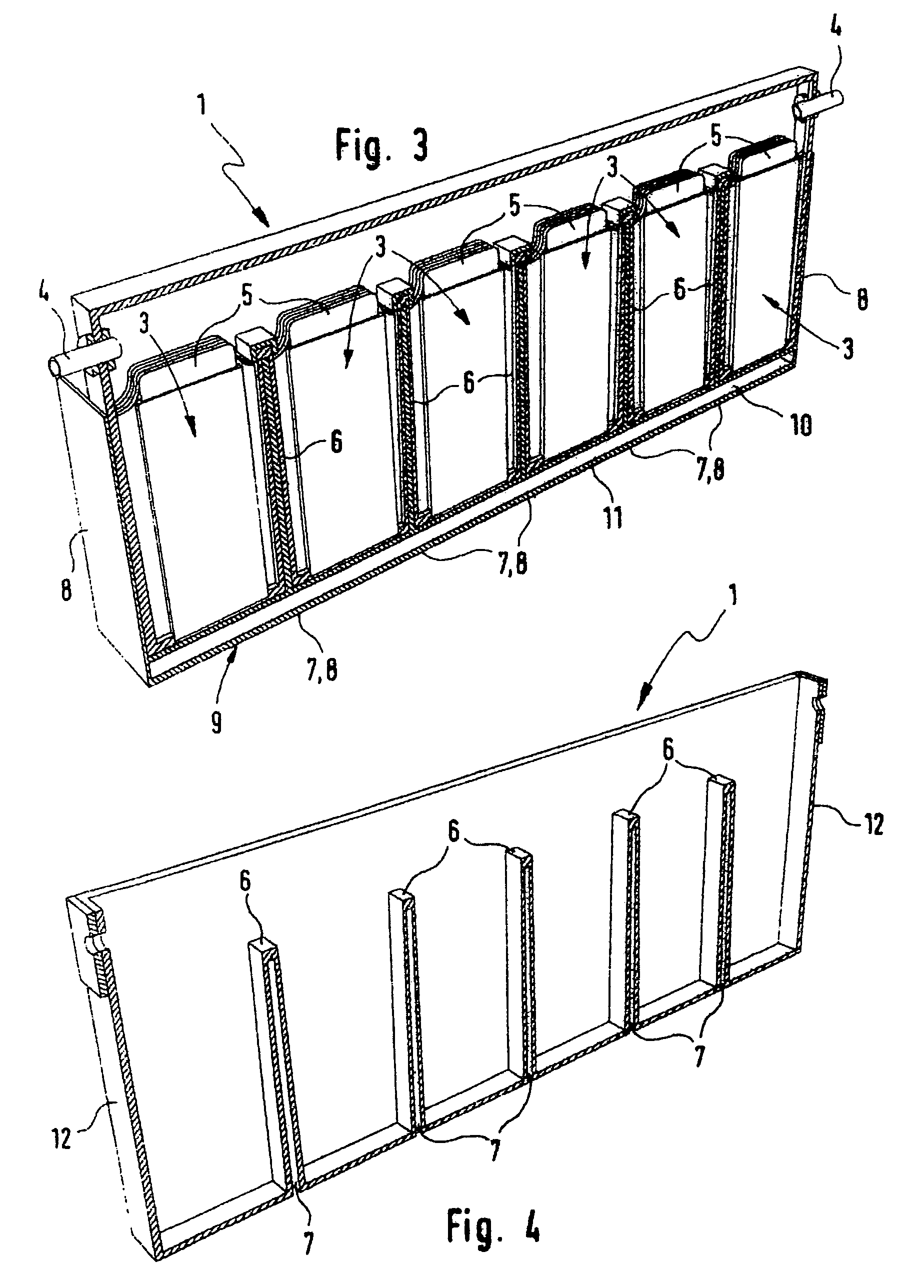
[0031]FIG. 2 shows a sectional view of a module 1 of this type in an embodiment according to the related art. In addition to the two electric connections 4, this illustration also shows individual electrochemical cells 3 inside module 1. Individual electrochemical cells 3 each include alternating vertically stacked electrodes which are typically designed as metal plates or metal films, and an active ground and electrolyte positioned therebetween. A number of these films serving as electrodes are shown schematically in FIG. 2 and are identified by reference numeral 5.

[0032]Module 1 illustrated here has 6 electrochemical cells 3 of ...


PUM

PropertyMeasurementUnit
dynamic temperatureaaaaaaaaaa
tensioning forceaaaaaaaaaa
areaaaaaaaaaaa

Abstract

A prismatic battery including multiple individual cells, at least two of which are combined to form a prismatic module. At least two of the modules, in turn, are stacked to form the battery and joined together under tension between two end plates. The prismatic battery also has at least one cooling member which is in heat-conducting contact with at least one of the modules. This cooling member has at least one cooling fin which is provided parallel to the direction of the tensioning force.

Description

[0001]Priority is claimed to German patent application DE 10 2005 031 504.6, filed Jul. 6, 2005, the entire disclosure of which is hereby incorporated by reference herein.[0002]The present invention relates to a prismatic battery made of multiple individual cells, at least two of which are combined to form a prismatic module, at least two of the modules being stacked to form the battery and joined together under tension between two end plates, having at least one cooling member which is in heat-conducting contact with the modules.BACKGROUND[0003]Batteries, in particular high-performance batteries based on nickel metal hydride or lithium, such as those frequently used in today's applications for driving vehicles, for example electric vehicles or hybrid vehicles, are typically made of stacked prismatic modules. Multiple modules of this type are then combined to form the battery. The individual modules include the electrochemical cells of the battery, multiple cells of this type typica...

Claims


Application Information

Patent Timeline
Patent Type & Authority Patents(United States)
IPC IPC(8): H01M6/46H01M50/296H01M50/503H01M50/557
CPCH01M2/0212H01M2/0242H01M2/206H01M10/0413H01M10/0468H01M10/5004H01M10/5008H01M10/5016H01M10/5032H01M10/5038H01M10/504H01M10/5059H01M10/5079Y02T10/7011H01M2/305H01M10/052H01M10/345H01M10/502H01M10/5087H01M2/0217H01M10/625H01M10/63H01M10/653H01M10/647H01M10/6569H01M10/652H01M10/6557H01M10/617H01M10/613H01M10/658Y02E60/10H01M50/103H01M50/557H01M50/296H01M50/503
Inventor WEGNER, BERND
Owner DAIMLER AG
Why Eureka
Try Eureka