Heart preservation chamber

Active Publication Date: 2009-08-11
TRANSMEDICS
View PDF46 Cites 58 Cited by
  • Summary
  • Abstract
  • Description
  • Claims
  • Application Information

AI Technical Summary

Benefits of technology

[0006]The heart preservation apparatus 10 of the present invention also solves the problems of prior organ chambers which suspend the heart by its vessels or allow it to lay on a flat surface. The present chamber has an inclined support surface 13a and inclined support surface 13b which meet at a chamber base 14, forming an inclined trough 12. The inclined trough has a concave cross-sectional shape along an axis of the chamber 10, in which the concave cross-sectional shape can be v-shaped or u-shaped. The v-shape is depicted at the point where the inclined

Problems solved by technology

However, such suspension of the heart by its vessels can cause problems of aorta tearing and heart ischemia over long periods of ti

Method used


Image

  • Heart preservation chamber
  • Heart preservation chamber
  • Heart preservation chamber

Examples


Embodiment Construction

[0010]A description of preferred embodiments of the invention follows.

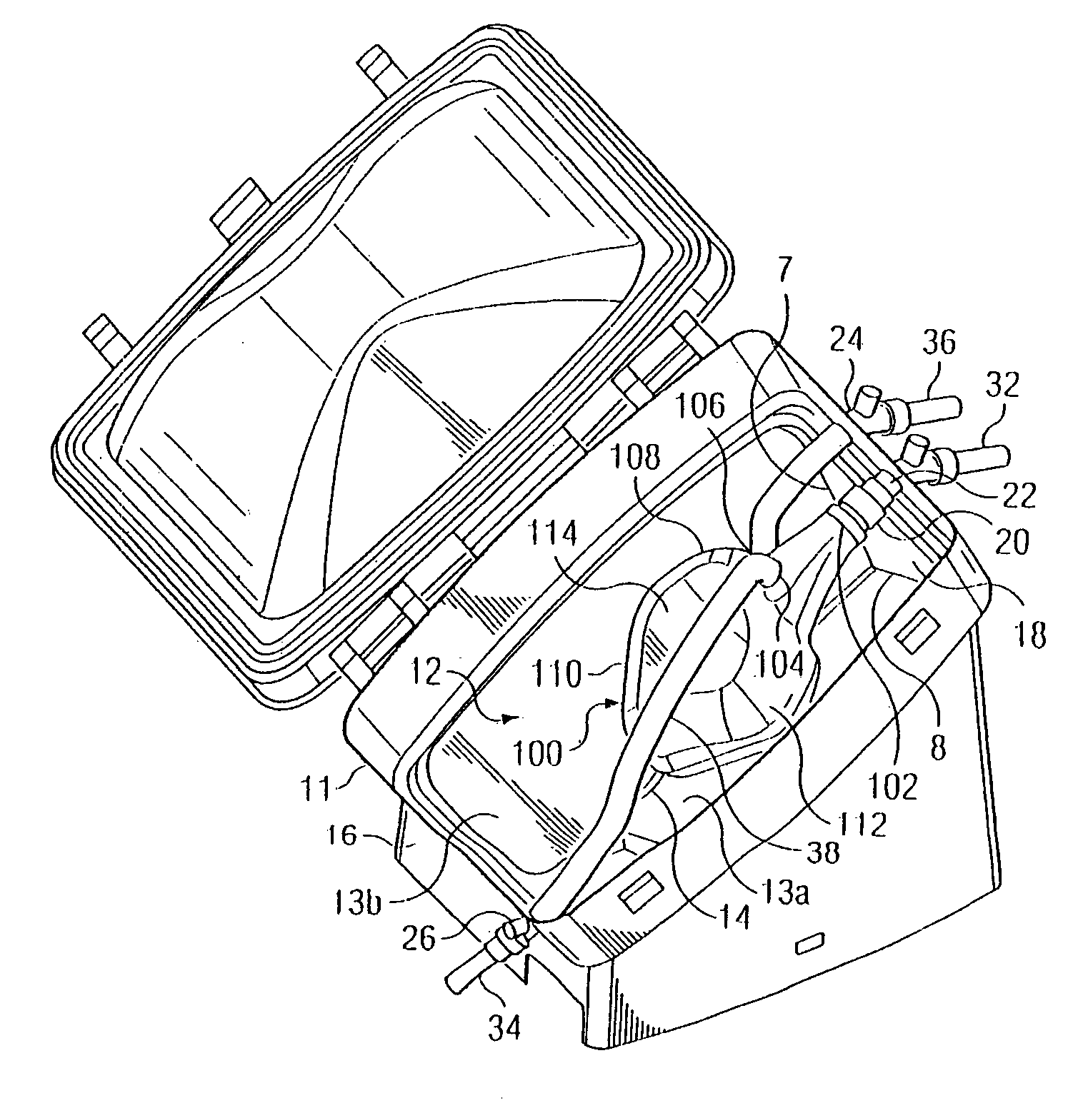
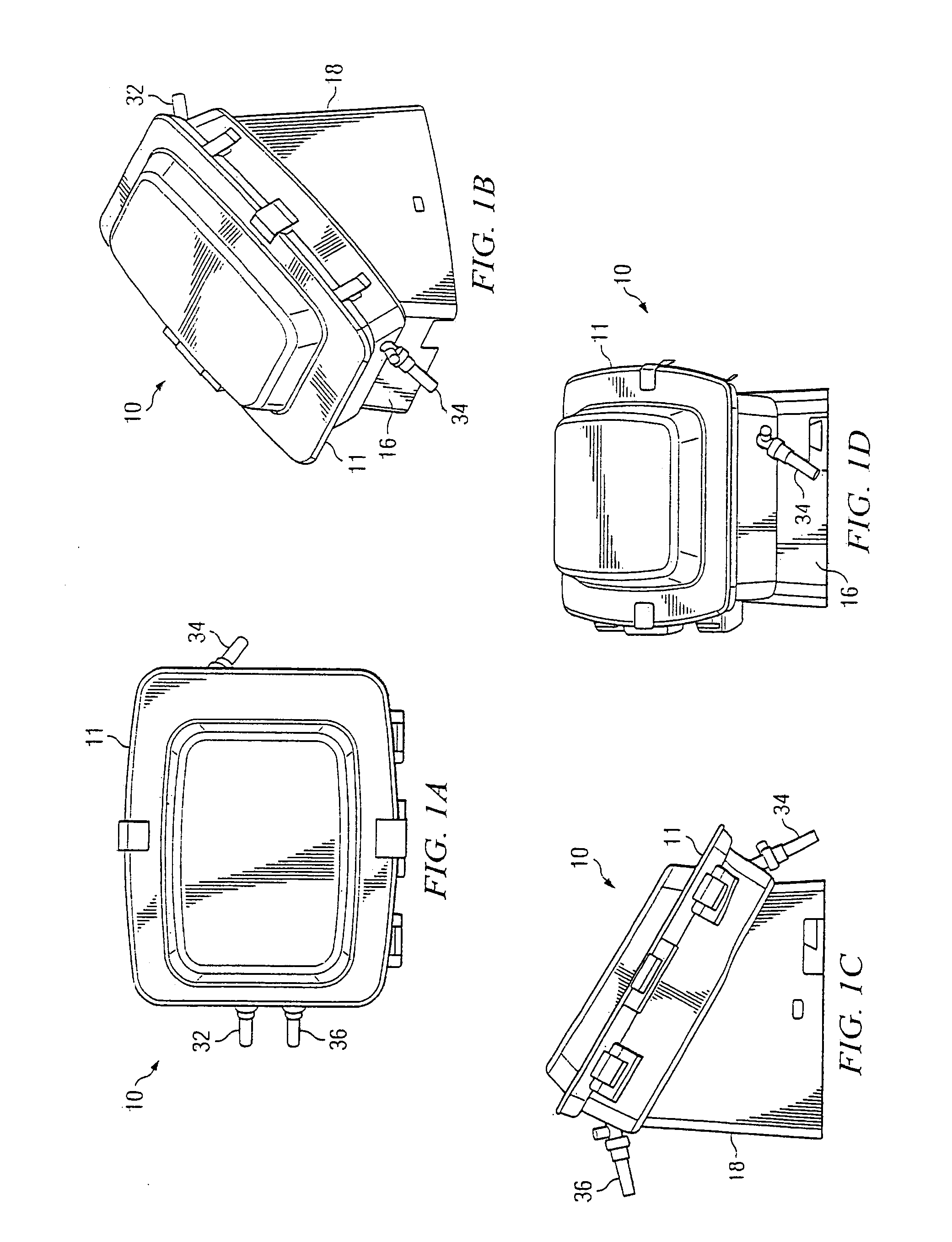
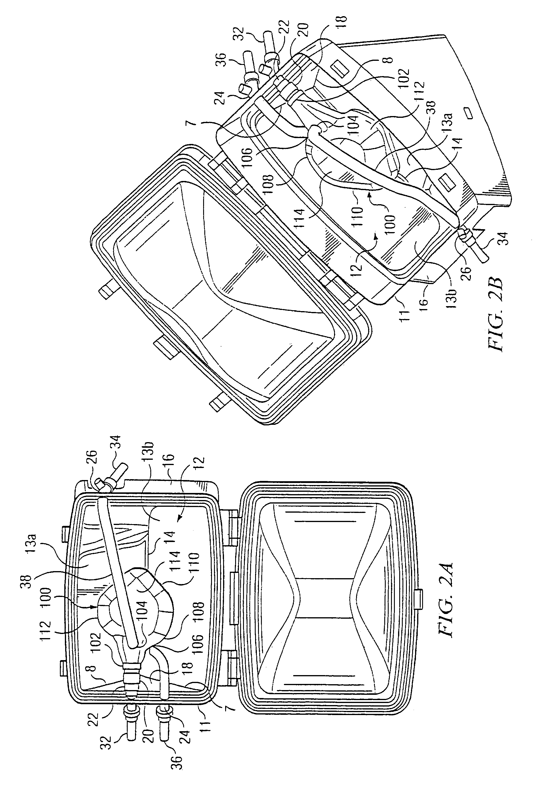
[0011]The heart preservation apparatus 10 comprises a housing 11 defining a chamber that typically is at least partially transparent, has an inclined trough 12, preferably v-shaped, for supporting the heart 100, and includes a connector 22 for the aorta 102 attached to the upper wall 18 of the apparatus 10, at least one other inlet means 24 attached to the upper wall 18 and at least one other outlet means 26, attached to a lower wall 16, through the walls of the chamber for connecting fluid from or to a preservation fluid circuit to the heart 100. Sterilized cable straps 20 tighten around the heart blood vessels, to the connectors, creating a leakproof seal with the chamber. In a preferred embodiment, the heart preservation apparatus 10 provides a sterile sealed, warm, moist environment for preserving and maintaining a viable, functioning heart 100.

[0012]The housing 11 typically is at least partially transparent t...


PUM


Abstract

A heart preservation chamber is disclosed which comprises a housing, an inclined trough support surface, and inlet and outlet fluid connections for the major heart blood vessels.

Description

RELATED APPLICATION[0001]This application claims the benefit of U.S. Provisional Application No. 60 / 403,556, filed Aug. 14, 2002. The entire teachings of the above application is incorporated herein by reference.BACKGROUND OF THE INVENTION[0002]This application relates to the field of heart preservation, resuscitation, evaluation and maintenance.[0003]Organ preservation devices, such as the POPS™ system designed by TransMedics, Inc., often require a specially designed chamber to house the organ. Examples of such organ preservation devices are described in U.S. Pat. Nos. 6,046,046 and 6,100,082, the entire teachings of which are incorporated herein by reference.[0004]Recent advances in the field of organ preservation have led to a desire to have the organ kept in a functioning and viable state during the preservation period. To do so, the organ must be maintained in a way that allows it to so function. Previous containers for the heart have been constructed to have the heart suspende...

Claims


Application Information

Patent Timeline
IPC IPC(8): A01N1/02
CPCA01N1/02A01N1/0273A01N1/0247
Inventor HASSANEIN, WALEED H.BRINGHAM, RICHARD L.TAYLOR, JR., RONALD L.
Owner TRANSMEDICS
Why Eureka
Try Eureka