Method and apparatus for data entry for a liquid crystal display

a liquid crystal display and data entry technology, applied in the field of liquid crystal display data entry, can solve the problems of reducing the quality of liquid crystal display, and increasing so as to achieve the effect of increasing reflection and/or image degradation, and not reducing the difficulty of viewing images

Inactive Publication Date: 2009-08-11
ROCKWELL COLLINS INC
View PDF11 Cites 19 Cited by
  • Summary
  • Abstract
  • Description
  • Claims
  • Application Information

AI Technical Summary

Benefits of technology

[0008]It is an advantage of the present invention to avoid the known shortcomings of the conductive layer and light transmitter / sensor pair type of touch screens.
[0009]The present invention is an apparatus and method for providing data entry, via touch screen, for an LCD which is designed to satisfy the aforementioned needs, provide the previously stated objects, include the above-listed features and achieve the already articulated advantages. The present invention is carried out in an “increased reflection-less and image degradation-less” manner in a sense that the increased reflection and / or image degradation associated with a conductive layer type of touch screen over the viewing surface has been eliminated, or at least greatly reduced. Additionally, the present invention is carried out in a “light pollution-less” manner in the sense that the undesirable light associated with the light transmitter / detector pair type of touch screen has been eliminated, or at least greatly reduced.
[0010]Accordingly, the present invention is an LCD touch screen system including a plurality of shockwave sensors disposed about the periphery of the viewing surface of an LCD, where the shockwave sensors detect shockwaves which emanate from a point on the screen that is touched.

Problems solved by technology

While these LCD touch screen systems may have many advantages in particular uses, they also have created challenges.
One common challenge created by the conductive layer type touch screen sensor is the degradation of the image to be viewed.
Another problem with the prior art light transmitter / sensor pair type of touch screen, in addition to the relatively high cost, occurs when these light transmitter / sensor pairs are used when a pilot is using a night vision imaging system, hereafter NVIS.
These light transmitters can interfere with the optimal performance of an NVIS.

Method used


Image

  • Method and apparatus for data entry for a liquid crystal display
  • Method and apparatus for data entry for a liquid crystal display

Examples


Embodiment Construction

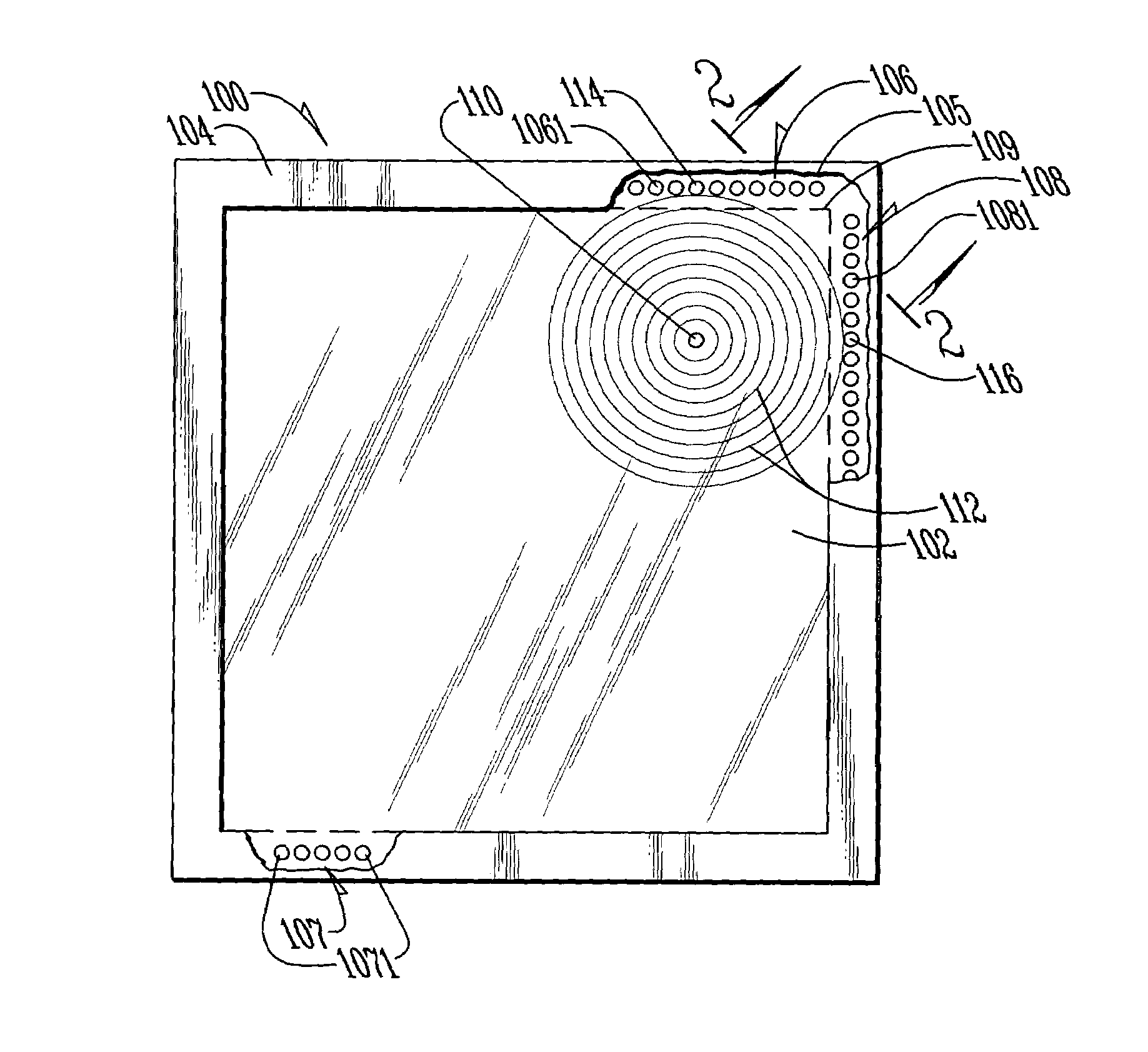
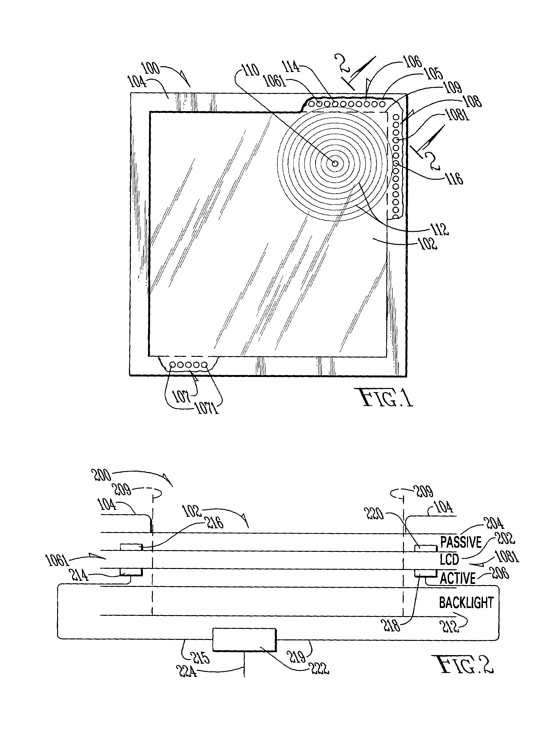
[0014]Now referring to the drawings wherein like numerals refer to like matter throughout, and more specifically to FIG. 1, there is shown an LCD with touch screen system of the present invention, generally designated 100. The description herein focuses upon LCD systems used in the cockpit of an aircraft because it is believed that many of the features of the present invention are particularly well suited for use in an aviation environment. However, it should be understood that other environments are equally applicable, and they are intended to be included within the scope of the present invention. LCD system 100 includes a viewing surface 102, which could be any type of liquid crystal material, but a multi-domain vertically aligned liquid crystal may be preferred. A bezel 104 is shown about the periphery of the viewing surface 102. A jagged cut-away line 105 represents an edge of a portion of the bezel 104 which is cut away. The dashed line 109 represents the location of the normal...


PUM


Abstract

A touch screen for LCDs which uses a plurality of shockwave detectors disposed around the periphery of the viewing area to detect the location of a touch or tap which is the point of origin of an expanding shockwave.

Description

FIELD OF THE INVENTION[0001]The present invention generally relates to liquid crystal displays (LCDs), and more particularly relates to touch screen data entry LCDs, and even more particularly relates to methods and apparatus for detecting a touch or tap upon a screen of LCDs.BACKGROUND OF THE INVENTION[0002]In the past, LCDs have been used in a wide variety of environments, including displays within the cockpit of an aircraft. In some aircraft, it is desirable to have touch screen LCDs. Many of these touch screen displays use transparent and conductive layers across the viewing surface to effect the touch screen capabilities. Other prior art systems use pairs of light transmitters and detectors disposed around the periphery of the display. These light transmitter and detector pairs are similar to what is shown in U.S. Pat. No. 3,775,560 assigned to the University of Illinois Research Foundation.[0003]While these LCD touch screen systems may have many advantages in particular uses, ...

Claims


Application Information

Patent Timeline
Patent Type & Authority Patents(United States)
IPC IPC(8): G06F3/043
CPCG06F3/0433G06F3/043
Inventor MARZEN, VINCENT P.STUPPI, ALBERT N.BISHOP, GARY D.BAHADUR, BIRENDRAJONES, MICHAEL R.
Owner ROCKWELL COLLINS INC
Why Eureka
Try Eureka