
Modular control system with terminal and function modules

a terminal module and module control technology, applied in the field of terminal modules, can solve the problems of st also failing to solve the problem, subsequently extending the control function, etc., and achieves the effect of simple and transparent handling, easy optical control of the structure, and maximum width of the width of the terminal modul

Inactive Publication Date: 2009-08-11
SIEMENS AG
View PDF8 Cites 4 Cited by
  • Summary
  • Abstract
  • Description
  • Claims
  • Application Information

AI Technical Summary

Benefits of technology

[0012]An object of the invention is create a control system with a modular structure with terminal modules and function units of the type mentioned in the background section, which reduces the outlay for planning and ordering as well as for assembly compared with known systems and renders re-arrangement of the terminal modules and the rewiring optionally associated therewith unnecessary during system extensions.
[0016]The inventive use of terminal modules of identical structure, the different functionalities of which are achieved by at least one additional mountable function unit, to construct a modular control system results in simpler and error-free pre-assembly of the standard terminal modules and significantly easier modification of the system configuration. The stocking of spare parts is simplified considerably for the user, particularly with a view to planned modifications and extensions.
[0018]In one similarly advantageous embodiment the function units have means for visualizing the functionality provided. This allows easy optical control of the structure and makes the entire control system readily transparent with regard to the supply of supply voltages, potential forwarding and separation and specialist functions.
[0019]In one particularly advantageous embodiment two adjacent terminal modules can be connected respectively by means of the function units and a maximum width of the width of a terminal module is provided for the function units. This means that the individual function units can be assembled together individually in a chain, the function units being mounted on the contacts of the respective terminal modules in the half-grid. If the function units have precisely the width of a terminal module, adjacent terminal modules are connected to the function units such that it is possible to line the function units up precisely next to each other. The use of function units, by means of which only two adjacent terminal modules are connected respectively, allows simple and transparent handling during gradual commissioning and it is possible to disconnect individual potential groups without detaching wires.

Problems solved by technology

A major disadvantage results in particular when control functions are subsequently extended.
Correspondingly configured terminal modules—as described above—are known from the Siemens ET 200S control system but these do not resolve this problem.
Other similar applications, for example Mitsubishi Electric's MELSEC ST also fail to resolve the problem.

Method used


Image

  • Modular control system with terminal and function modules
  • Modular control system with terminal and function modules
  • Modular control system with terminal and function modules

Examples


Embodiment Construction

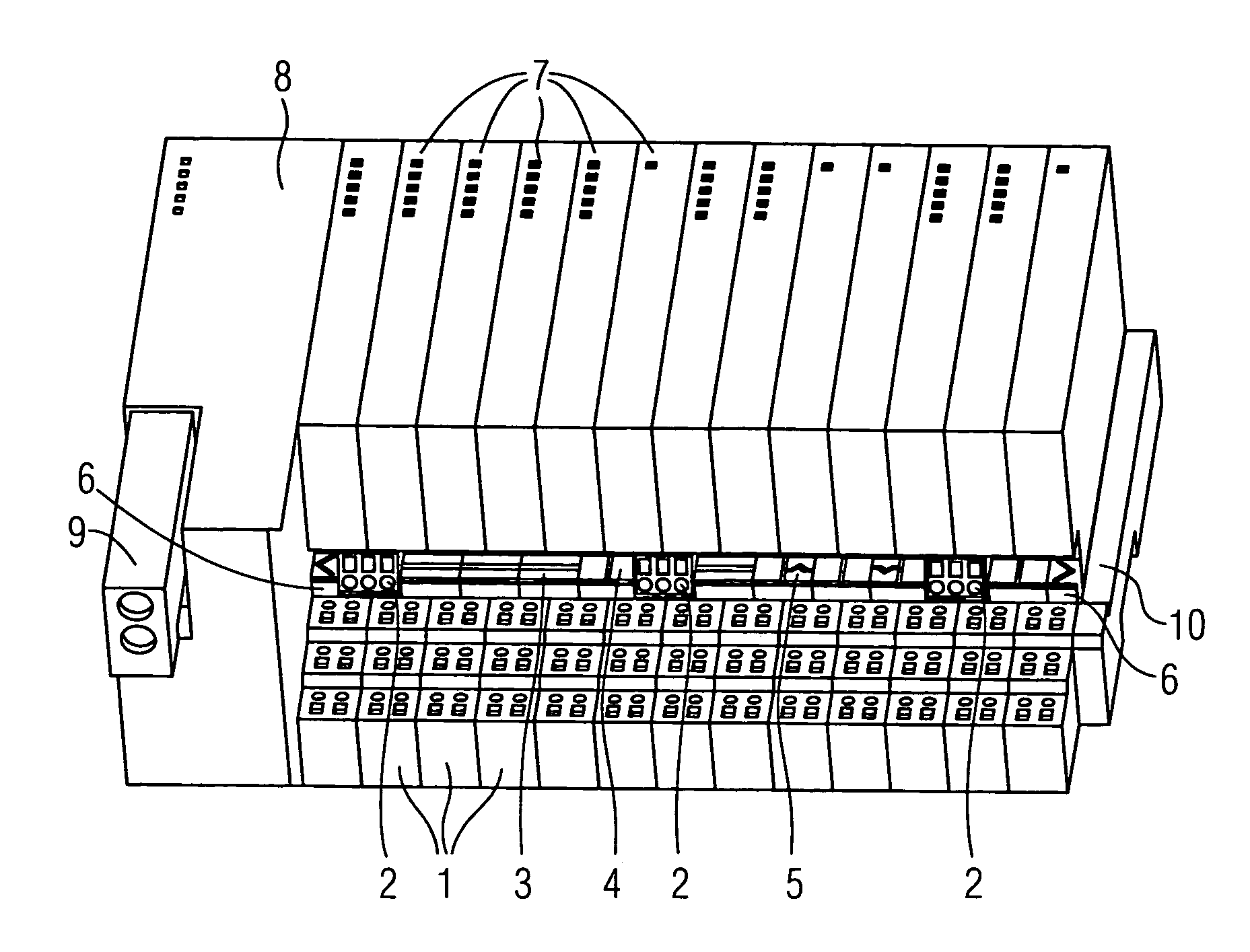
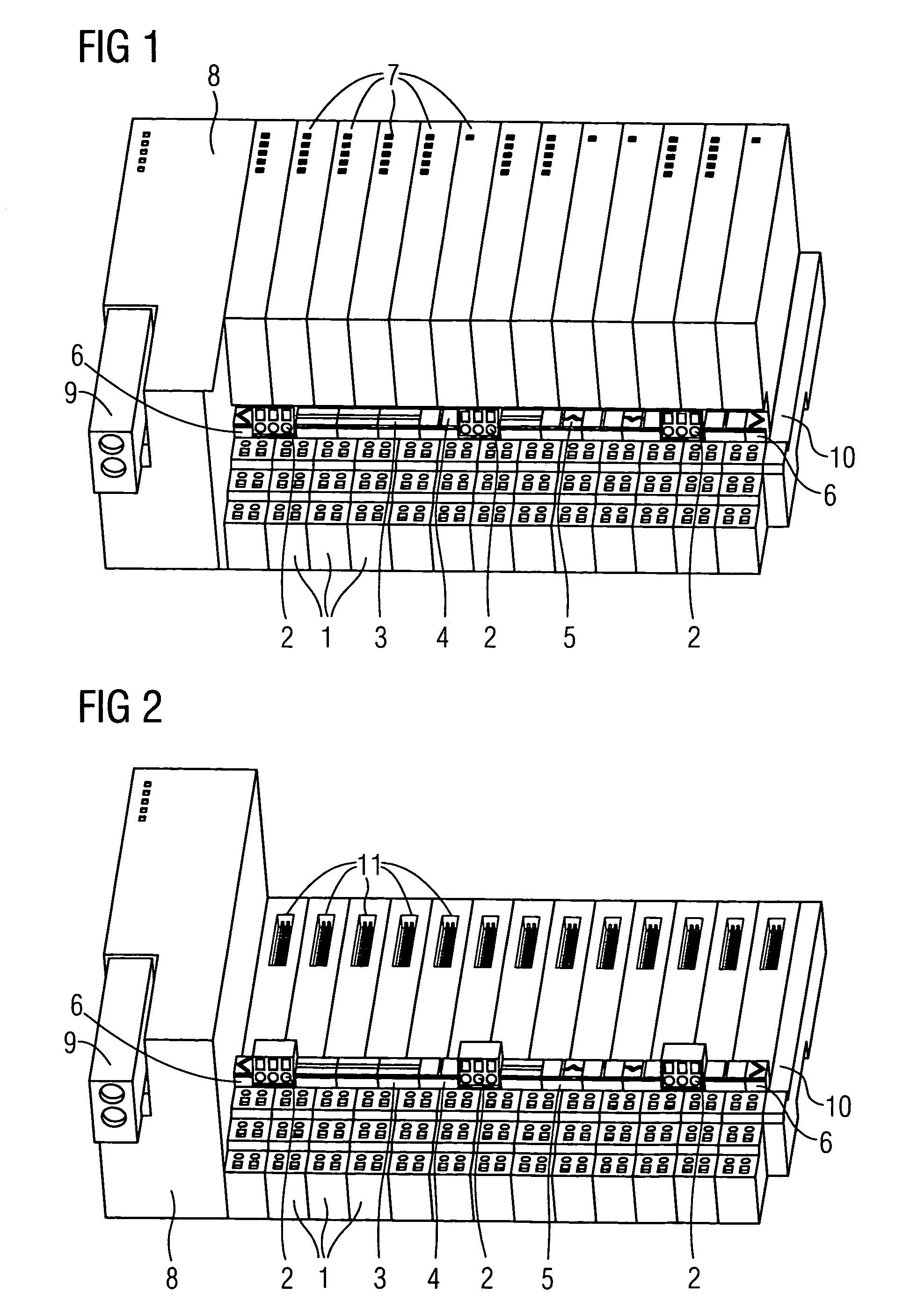
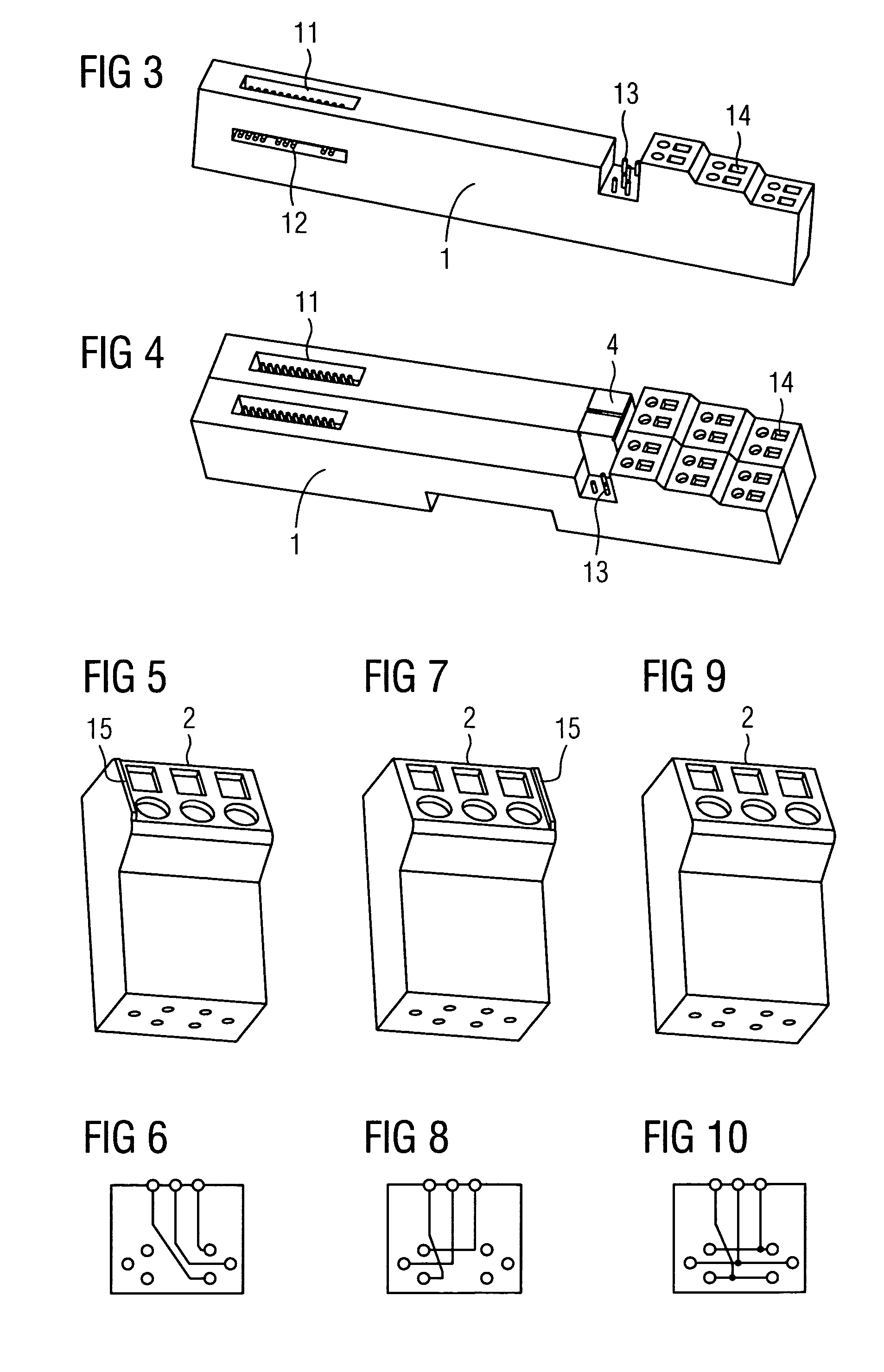
[0049]FIG. 1 shows an exemplary embodiment of the inventive control system, comprising a chain of terminal modules 1 with terminals 14, on which function modules 7 are mounted. At the start of the chain of terminal modules 1 is an interface module 8 with an interface terminal connector 9, with a termination module 10 forming the end of the chain. In this exemplary embodiment the function units only connect two adjacent terminal modules 1 respectively, with the width of the function units corresponding precisely to the width of a terminal module 1. The FIG. shows three supply units 2 with three terminals for the power supply and a PE connection. There are also bridge units 3 and separator units 4, which are easy to distinguish due to their different markings 15. There are also two specialist units 5; the start and end of the chain of function units are each formed by one termination unit 6.

[0050]FIG. 2 shows the same exemplary embodiment as in FIG. 1 but without the function modules ...


PUM


Abstract

A modular control system, which is constructed from terminal modules and function modules to fit these, for use in industrial automation in particular is provided. With the known embodiments, which comprise different terminal modules for different functionalities, subsequent system extensions can often only be achieved with significant outlay. With the inventive modular control system this problem is resolved by the use of novel terminal modules of identical structure, with the different functionalities being provided by additional function units. Additional advantages, in addition to simpler modification of the system configuration, are lower planning and assembly outlays, simpler and error-free pre-assembly of the standard terminal modules, simpler stocking of spare parts, clear transparency in respect of the supply of supply voltages, potential forwarding and separation and specialist functions such as simple and transparent handling during gradual commissioning.

Description

CROSS REFERENCE TO RELATED APPLICATIONS[0001]This application claims priority of European application No. 05020253.0 EP filed Sep. 16, 2005, which is incorporated by reference herein in its entirety.FIELD OF INVENTION[0002]The invention relates to a terminal module with terminals, on which a function module can be mounted, for the modular construction of a control system, the terminal module having contacts on both sides, which are connected internally to each other for electrical purposes and also have electrical connections to the interface for the function modules. The invention also relates to a function unit and a control system with a module structure, having at least two such terminal modules and at least one such function unit.BACKGROUND OF INVENTION[0003]Such a system is used in particular in the field of industrial automation. Industrial controllers with a modular configuration are frequently sub-divided into terminal modules and function modules to fit these (digital or a...

Claims


Application Information

Patent Timeline
Patent Type & Authority Patents(United States)
IPC IPC(8): G05B15/00G06F11/00
CPCH01R9/2675H05K7/1478H05K7/1465H01R9/2683
Inventor BRAUNLICH, MICHAELMEIER, FRANK-GUNTER
Owner SIEMENS AG
Learn More