
Automated generation of lean models for injection molding simulation

a technology of injection molding simulation and automatic generation, applied in the field of computer simulation of fluid flow, can solve the problems of inability to accurately predict the flow of fluid, etc., to achieve the effect of simplifying the use of injection molding simulation software, improving robustness, and routinely and reliably using

Active Publication Date: 2009-08-11
PROTOMOLD CO THE
View PDF6 Cites 41 Cited by
  • Summary
  • Abstract
  • Description
  • Claims
  • Application Information

AI Technical Summary

Benefits of technology

"The invention is a method and system for automated generation of models for fluid flow simulation in thin cavities, such as injection molding of plastic parts. The method uses a simplified, locally 1D, treatment of balance equations in macrocells, even in irregularly shaped macrocells reflecting complexities of part geometry. The method also includes steps involved in automated partitioning of the cavity, no matter how complex and convolved, and selecting nodal points and sampling points inside the cavity. The invention improves the robustness and simplifies the use of injection molding simulation software, making it more routinely and more reliably used in the design and manufacturing of plastic parts."

Problems solved by technology

Computer models for simulation of injection molding have been developed and implemented in sophisticated and expensive commercially available software.
Model simulations can forecast the likelihood that, for example, the resin will not entirely fill the cavity before it freezes; regions of weakness (e.g, weld lines) may be present in the molded plastic part; air traps might occur causing unfilled bubbles in the molded part; or the molded part might have unacceptable sink marks, burns or other blemishes.
An unfavorable result from a simulation may lead to a redesign of the mold or of the part, or even to termination of the project.
Building the flow model may take considerable time, but even more time is often spent running simulations with the model.
Simulations that are slow to execute are costly, in terms of both consumption of computer resources and time elapsed on the wall clock while people are waiting to analyze the results.
Solving very large models with computing resources typically available in the industry can be unacceptably slow and impractical.
It should be noted that turbulent diffusion of heat, a third process important in some fluid flow contexts, is unimportant to injection molding because the melt is strongly viscous, resulting in laminar flow.
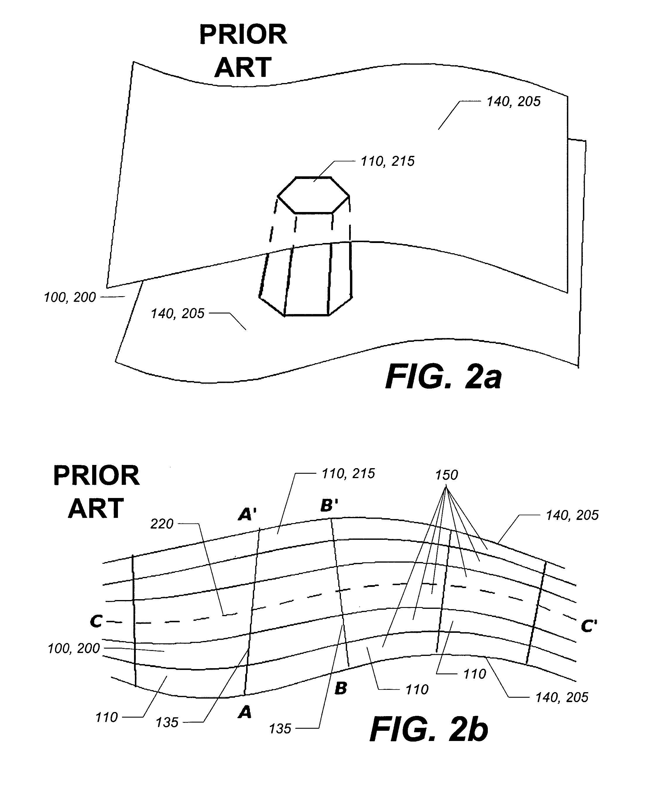
The classical HS approximations do not work near intersections, as the standard flat and cylindrical elements cannot approximate the local geometry.
Early implementations of 2.5D modeling required labor-intensive involvement of highly skilled technicians in the semi-manual construction of branched 2D meshes and assigning effective geometric characteristics to elements as needed to create complete flow models.
Attempts to generate 2.5D models by automating the construction and consequent meshing of midsurfaces had little or no success, partly because the necessary mathematical generalization of midsurface, the skeleton, is a complex geometric object for non-trivially shaped parts.
It appears, however, that more complex thin-walled parts, in particular parts with numerous shallow features, may still be problematic for DUALDOMAIN technology.
For example, serration and other intricate features on a large area of the part surface may result in a massively incorrect element matching, as well as lead to erroneous thickness assignments.
But defeaturing can be a labor-intensive operation on par with the semi-manual midsurface construction, especially if it has to be done after the part geometry is exported out of the CAD program in which it was designed.

Method used


Image

  • Automated generation of lean models for injection molding simulation
  • Automated generation of lean models for injection molding simulation
  • Automated generation of lean models for injection molding simulation

Examples


Embodiment Construction

Classical Hele-Shaw Geometries

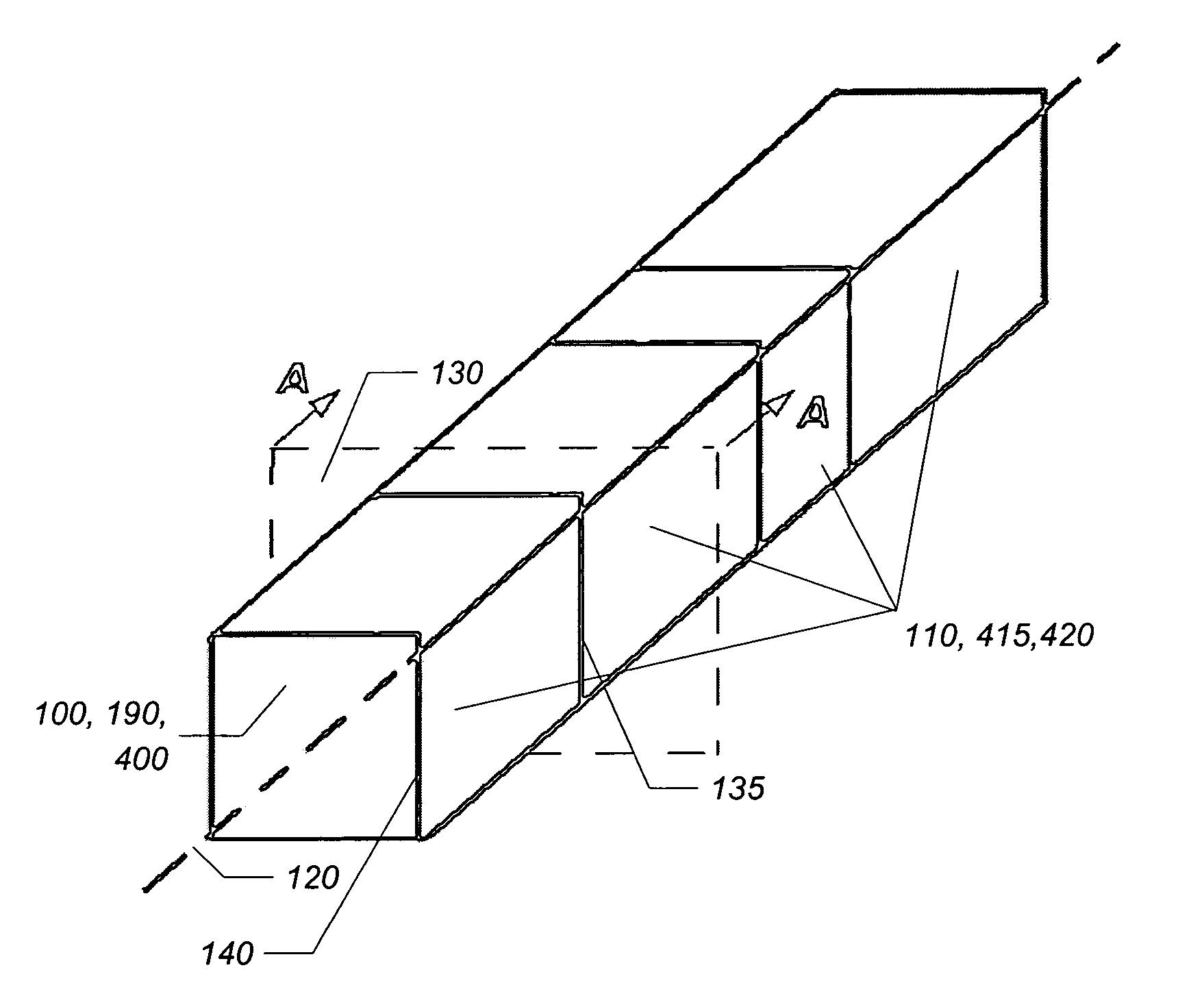
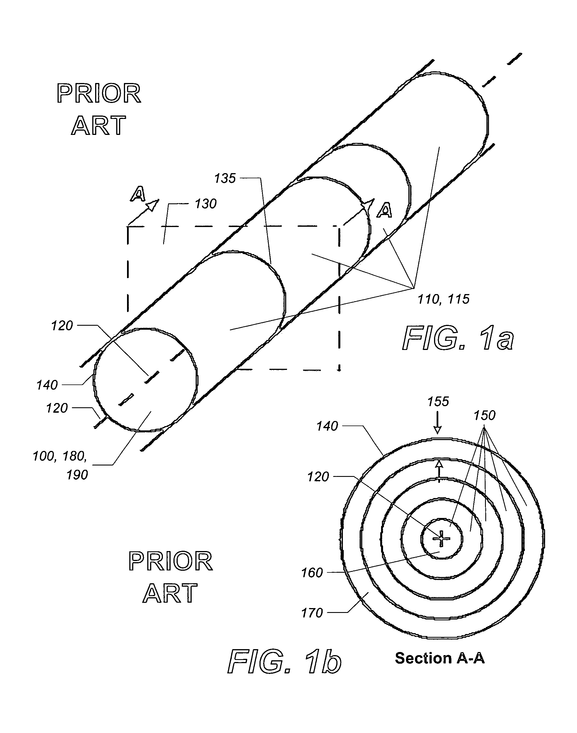
[0054]FIG. 1a and FIG. 1b illustrate one of the two kinds of mold cavity 100 geometries that can be handled using the classical HS approximations, namely, a runner 190 shown here in the shape of a straight cylindrical cavity 180. The runner 190 is divided along its axis 120 into cells 110, specifically cylindrical cells 115. Any two adjacent cells 110 are joined at an interface 135. A cross-section 130 (FIG. 1b) shows that the cylindrical cells 115 are divided into layers 150, which are part of the discretization scheme of the model. Flow, in this case 1D flow along the axis 120 of the runner 190, will be generally parallel to the walls 140. In the i-th cell, each layer 150 has a characteristic layer thickness 155 hi,k, where k is the layer 150 index, increasing inward from 1 in the layer closest to the wall. The layer thickness 155 of the innermost layer 160 is defined as the distance from the axis 120 to the boundary with the next layer 150. The exemp...


PUM

PropertyMeasurementUnit
shapeaaaaaaaaaa
contact areaaaaaaaaaaa
volumeaaaaaaaaaa

Abstract

The present invention is a method and system for simulating fluid flow in a cavity, having relevance to the modeling of viscous flows within thin cavities of complex shapes in which heat exchange with the cavity walls may be a governing factor, as in injection molding of plastic parts. Its automated discretization scheme, in which the model cavity is partitioned into macrocells, each macrocell having substantial contact areas with the model cavity walls, eliminates the need for time consuming and expensive manual model configuration required by some modeling methods. Because of the simplicity of the discretization, models based on the invention are less demanding on computer resources then conventional finite element methods, and execute more quickly. A key innovation of the method is a function characterizing the shape of a macrocell that appears in a coefficient in equations governing the flow. As a consequence of the improvements offered by the invention, molds for complex parts can be fabricated more rapidly, with the resulting parts having high quality.

Description

FIELD OF THE INVENTION[0001]The present invention relates to the computer simulation of fluid flows and its industrial applications. More particularly, it relates to the modeling of viscous flows within thin cavities of complex shapes in which heat exchange with the cavity walls may be a governing factor, as in injection molding of plastic parts.BACKGROUND OF THE INVENTION[0002]In injection molding, a very viscous molten polymer material, or resin, is forced to flow under high pressure into a mold cavity, essentially corresponding in shape to the desired part, until the resin completely fills the cavity. During the filling, the molten resin (or melt) begins to cool, eventually solidifying into the plastic part.[0003]In addition to the portion of the mold cavity that reflects the shape of the desired part, the mold cavity may include runners (ducts through which molten resin flows from the nozzle of an injection molding press) ending in gates (determining injection locations and free...

Claims


Application Information

Patent Timeline
Patent Type & Authority Patents(United States)
IPC IPC(8): G06G7/50
CPCG06F17/505G06F30/327
Inventor LUKIS, LAWRENCE J.DREIZIN, YURI
Owner PROTOMOLD CO THE
Learn More