Tubular radial pin tumbler lock

a technology of tubular pins and tumbler locks, applied in the field of split pin tubular pin tumbler locks, can solve the problems of poor key control, easy picking or being drilled into locks, and the solution does not address the problem of picking, so as to prevent drilling on the axis

Active Publication Date: 2009-08-18
LOCKING SYST INT
View PDF23 Cites 13 Cited by
  • Summary
  • Abstract
  • Description
  • Claims
  • Application Information

AI Technical Summary

Benefits of technology

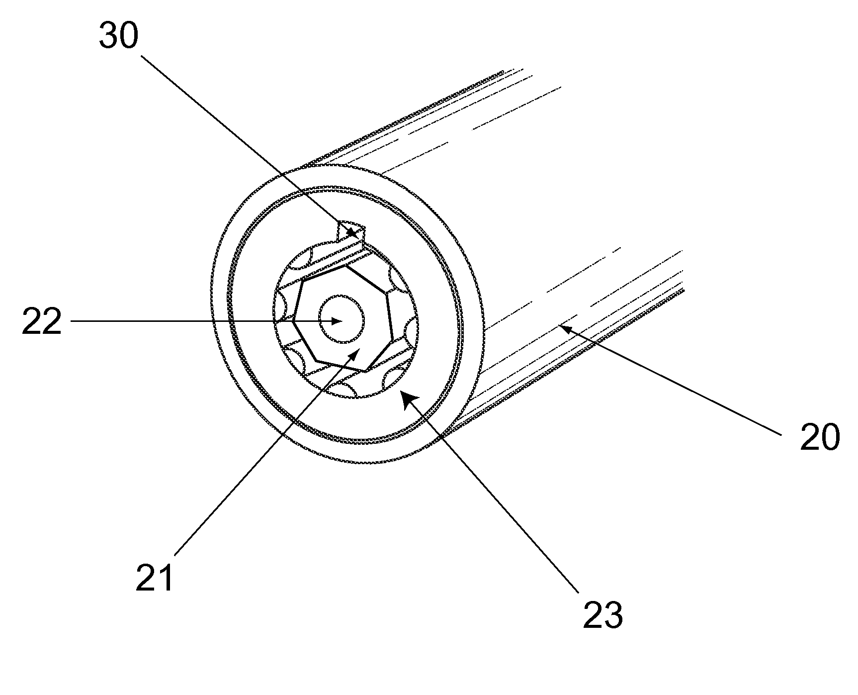
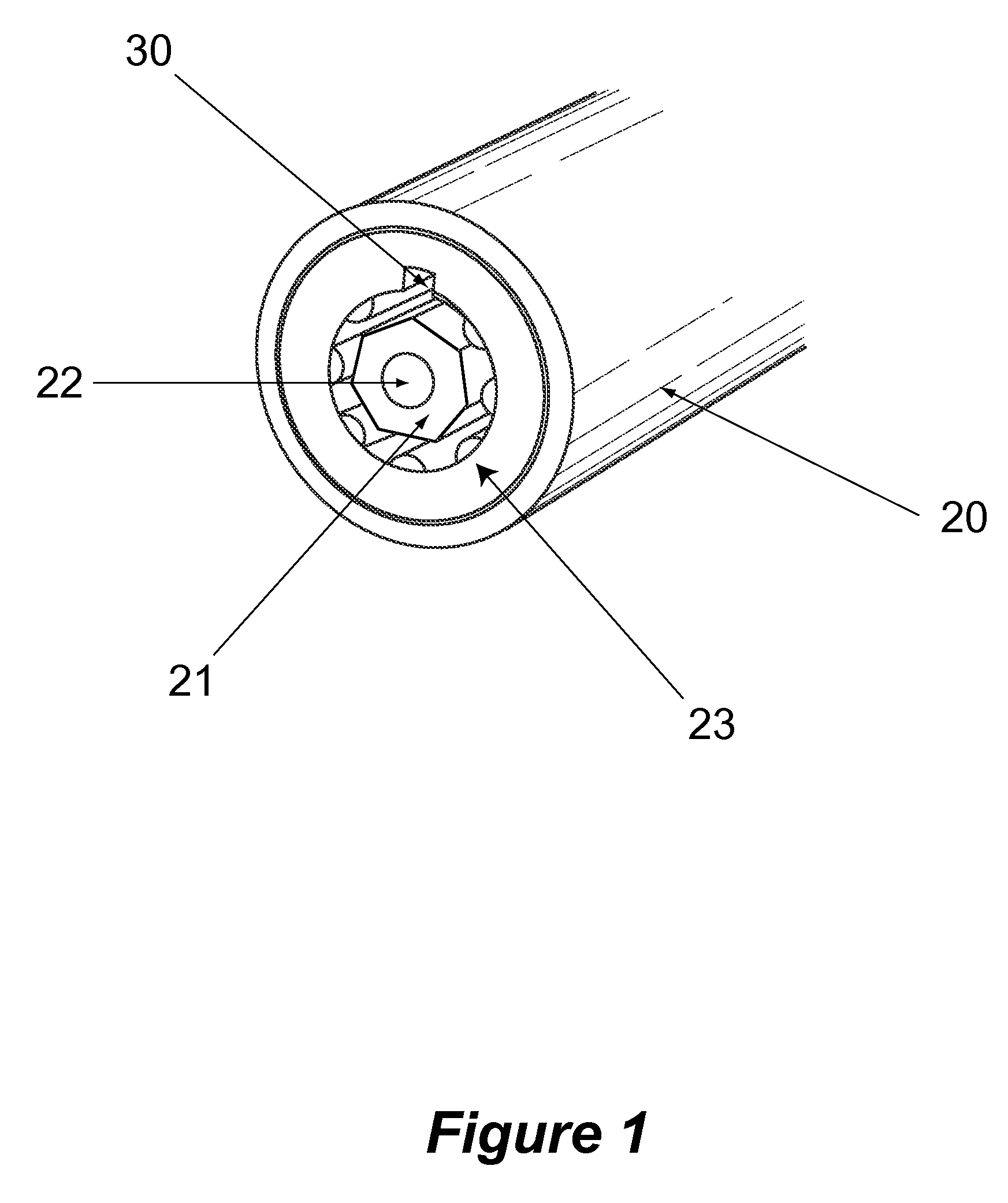
[0018]In yet another embodiment of the present invention, a radial pin tumbler locking apparatus having a means for receiving a tubular key having an uneven number of irregular surfaces interior to the tubular key and parallel to an axis of the tubular key, a means for encasing locking pins arranged to engage the tubular key when the tubular key is received, and a means for preventing drilling on an axis of the receiving means is described.

Problems solved by technology

A weakness of conventional tubular radial pin tumbler locks is poor key control because of a limited number of keyways available for the locks.
Another problem with conventional tubular radial pin tumbler locks in that these locks are prone to picking or being drilled into in order to open the lock.
These solutions do not address the picking problems with picking tools that fit over a round spindle, in the above previous solutions the changes were made to the outside diameter of the key which mates to the corresponding change to the shell.
However, these solutions provide regularly shaped keys such as, but not limited to an octagon, which does not provide additional keyways since all of the sides are equal.
However, the use of multiple keys can be inconvenient for users.
However, no prior art provides substantial drill protection.

Method used


Image

  • Tubular radial pin tumbler lock
  • Tubular radial pin tumbler lock
  • Tubular radial pin tumbler lock

Examples


Embodiment Construction

[0020]The present invention is best understood by reference to the detailed figures and description set forth herein.

[0021]Embodiments of the invention are discussed below with reference to the Figures. However, those skilled in the art will readily appreciate that the detailed description given herein with respect to these figures is for explanatory purposes as the invention extends beyond these limited embodiments. For example, it should be appreciate that those skilled in the art will, in light of the teachings of the present invention, recognized a multiplicity of alternate and suitable approaches, depending upon the needs of the particular application, to implement the functionality of any given detail described herein, beyond the particular implementation choices in the following embodiments described and shown. That is there are numerous modifications and variations of the invention that are too numerous to be listed but that all fit within the scope of the invention. Also, s...


PUM


Abstract

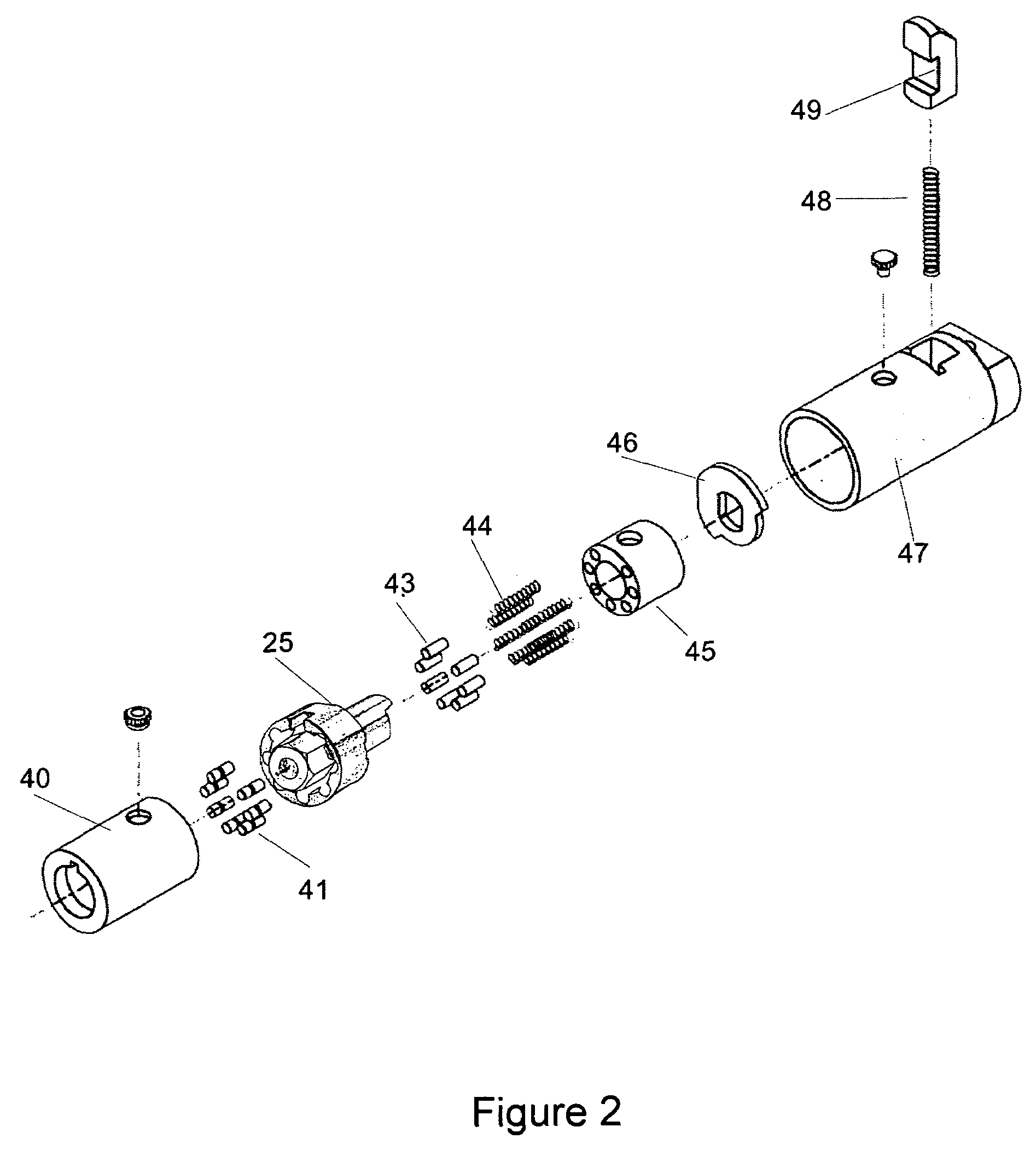
A tubular radial pin tumbler lock is described. The radial pin tumbler lock has an outer shell, an inner shell housed in the outer shell, and a spindle housed in the inner shell. The spindle has a spindle head with an uneven number of irregular sides. A plurality of radial locking pins are arranged radially from the spindle. A crown on the spindle encases the locking pins. An anti-drill feature is included on the spindle head. An annular space between the inner shell and the spindle head allows access to the radial locking pins for operating the radial pin tumbler lock.

Description

FEDERALLY SPONSORED RESEARCH OR DEVELOPMENT[0001]Not applicable.REFERENCE TO SEQUENCE LISTING, A TABLE, OR A COMPUTER LISTING APPENDIX[0002]Not applicable.COPYRIGHT NOTICE[0003]A portion of the disclosure of this patent document contains material that is subject to copyright protection. The copyright owner has no objection to the facsimile reproduction by anyone of the patent document or patent disclosure as it appears in the Patent and Trademark Office, patent file or records, but otherwise reserves all copyright rights whatsoever.FIELD OF THE INVENTION[0004]The present invention relates generally to locks. More particularly, the invention relates to a split pin tubular pin tumbler lock with an irregularly shaped and sided spindle heads, an anti-drill dimple or ball, and a crown on the spindle to protect the pins.BACKGROUND OF THE INVENTION[0005]A weakness of conventional tubular radial pin tumbler locks is poor key control because of a limited number of keyways available for the l...

Claims


Application Information

Patent Timeline
Patent Type & Authority Patents(United States)
IPC IPC(8): E05B19/02E05B27/08
CPCE05B27/083E05B15/1614Y10T70/7593Y10T70/7853Y10T70/7921
Inventor ULIANO, GEORGE
Owner LOCKING SYST INT
Why Eureka
Try Eureka