Designing drilling pattern for excavating rock cavern

a drilling pattern and rock cavern technology, applied in the direction of process and machine control, instruments, computer control, etc., can solve the problems of insufficient accuracy in the blasting of a round, significant inaccuracy, etc., to achieve the effect of convenient addition and removal, convenient modification of locations and other properties, and versatile editing

Active Publication Date: 2012-07-03
SANDVIK MINING & CONSTR OY
View PDF8 Cites 10 Cited by
  • Summary
  • Abstract
  • Description
  • Claims
  • Application Information

AI Technical Summary

Benefits of technology

[0009]An advantage of the invention is that the planning of the drilling pattern is more illustrative than previously, since the space to be generated is being planned instead of concentrating on the determination of the starting locations of the drill holes, as in conventional planning manners. Furthermore, thanks to a blasting-technical examination, the locations of the bottoms of the holes to be drilled may be determined according to the requirements of the blasting. This being so, the drill holes are in the correct location at the bottom of the round as regards the blasting, and, on the other hand, the drilling of extra holes is avoided. In addition, rock can be made to detach efficiently during blasting. Furthermore, when rock is caused to be detached in the planned manner during blasting, the quality of the rock cavern to be generated may be better. The planning carried out at the bottom of the round, together with the blasting-technical examination, also facilitates the determination of the charging. The determination of the specific charge for the different sections of the drilling pattern is easier and more illustrative to perform at the bottom of a round than at the navigation plane. Typically, the specific charge cannot be determined correctly in all sections of the drilling pattern until after up to 10 to 20 blasts, after the analysis of each blast result and the iteration of the blasting values. Now, when planning is carried out at the bottom of the round and the blasting-technical examination is taken into consideration therein from the beginning, the values of the specific charge can be determined correctly after only a few rounds.
[0014]The idea of an embodiment is to determine cracking zones at least for the drill holes of the end profile on the basis of the charge data of each drill hole. The cracking zones of the drill holes in the end profile are then compared with a predetermined, allowed cracking zone at least at the bottom of the round, and an indication is given to the user if the cracking zone of even one single drill hole is greater than the allowed cracking zone. On the other hand, the cracking zones may be displayed on the display of the designing computer in a manner allowing the designer to actively take the cracking zones into consideration during the planning. Thus, the designer is able to immediately modify the parameters of the drilling pattern so as to manage cracking. The cracking zones may be displayed on the display at the same time as the drilling pattern is being designed. If need be, the examination of the cracking zones may be carried out not only for the end profile, but also at least for the drill holes of the outermost aid row. Let it be mentioned that the end profile is a line passing through the drill hole bottoms of the outermost group of holes, and the aid rows, in turn, are groups of holes located inside the end profile, which also comprise a plurality of drill holes. On the basis of the examination of the cracking zones, the designer is able to modify the drilling pattern designed in a manner eliminating any exceeding of the allowed cracking zone. The quality requirements set in advance by the orderer of the rock cavern may thus be taken into consideration in the planning of each round.
[0016]The idea of an embodiment is to determine a plurality of locations for the drill hole bottoms for the end profile at the blast plane at a distance equal to the size of the desired hole intervals E from each other and to then determine burdens V for these drill holes. For calculating the burdens V, a blasting-technical calculation is performed for the drill holes at the blast plane. Furthermore, a burden line is determined at the ends of the burdens determined for the drill holes of the end profile inside the end profile. The outermost aid row is placed on the burden line of the end profile. A plurality of drill hole bottom locations is then determined on the outermost aid row at the blast plane at a distance from each other equal to the size of the desired hole intervals. The end profile, the burden line and the drill hole bottom locations may be presented visually in a graphic user interface. Blasting-technical planning enables a more accurate determination of the burden and, consequently, the number of holes to be drilled may be decreased in some cases as compared with a drilling pattern designed in a conventional manner. The drilling time naturally shortens, since no extra holes are drilled.
[0023]The idea of an embodiment is to predetermine the hole spacing between the drill hole bottoms in a group of holes. Thereafter, the drill hole bottom locations are placed automatically in the group of holes by means of the drilling pattern design program, taking account of the determined hole spacing. Alternatively, the desired section of a group of holes may be manually marked off and drill hole bottom locations may be automatically placed onto said marked-off section by means of the drilling pattern design program in accordance with the predetermined hole spacing. Still another alternative is to manually determine some desired part of a group of holes and to manually determine the number of drill holes in said section of the group of holes. Then the drilling pattern design program is allowed to automatically place the drill hole bottom locations at equal distances onto the selected section of the group of holes. Automatic functions in the drilling pattern design program for positioning drill hole bottoms into a group of holes substantially facilitate and speed up the designer's work. The designer may assign routine tasks to the drilling pattern design program for execution. On the other hand, later editing of the drilling pattern is also easy and fast.
[0028]The idea of an embodiment is that the designer determines at least two master holes in at least one group of holes of the drilling pattern, between which is arranged one or more intermediate holes. Furthermore, the designer determines one or more dominating properties for the master holes, for instance one of the following. location in the group of holes, depth, hole direction angle, degree of charge, hole spacing. In this case, the drilling pattern design program is able to calculate one or more properties of the intermediate hole on the basis of the dominating properties of the master holes. The group of holes may be an end profile, an aid row or a field hole element. An advantage of the use of master holes is that they significantly speed up the designing of the drilling pattern. Furthermore, the use of master holes facilitates later modification of the drilling pattern, since the designer is able to conveniently change the values of the master holes, whereby the drilling pattern design program again calculates new values for the intermediate holes. In addition, the designer is able to modify the drilling pattern by removing and adding master holes.

Problems solved by technology

Furthermore, rock blasting and rock detachment are three-dimensional events that are difficult to examine from the navigation plane.
In addition, drilling patterns designed at the navigation plane have been found to contain significant inaccuracies particularly at the corners of the pattern, which results from the look-out angles of the profile holes of the pattern.
Consequently, the problem in drilling patterns designed at the navigation plane is in that they do not achieve a sufficiently good accuracy in the blasting of a round.

Method used


Image

  • Designing drilling pattern for excavating rock cavern
  • Designing drilling pattern for excavating rock cavern
  • Designing drilling pattern for excavating rock cavern

Examples


Embodiment Construction

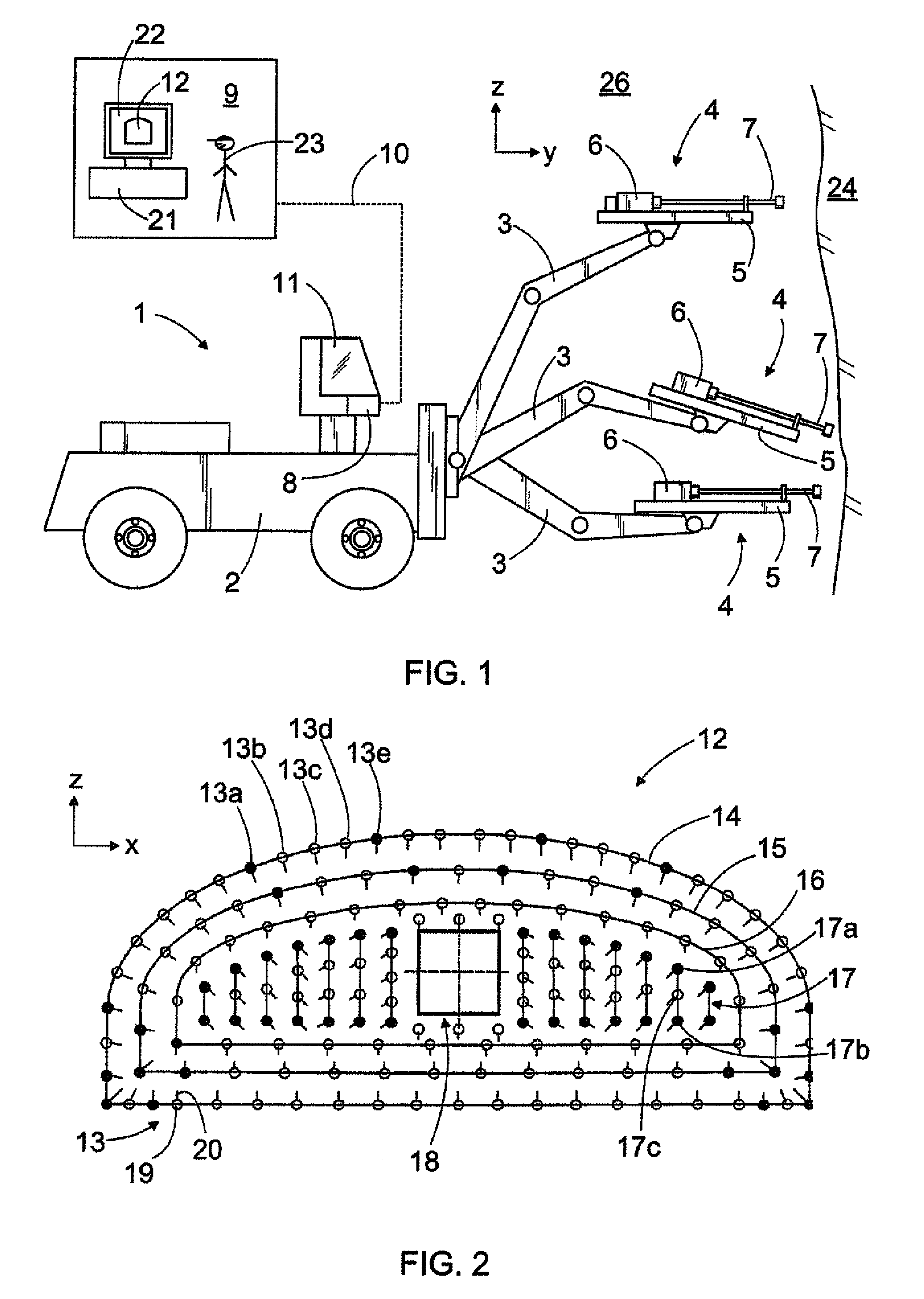
[0052]FIG. 1 shows a rock-drilling rig 1 comprising a movable carrier 2, one or more drilling booms 3 and drilling units 4 adapted to the drilling booms 3. The drilling unit 4 comprises a feeding beam 5 for moving a rock-drilling machine 6 by means of a feeding device. Furthermore, the drilling unit 4 comprises a tool 7 for transmitting impacts issued by the percussion device of the rock-drilling machine to the rock to be drilled. The rock-drilling rig 1 further comprises at least one control unit 8 adapted to control actuators belonging to the rock-drilling rig 1. The control unit 8 may be a computer or a corresponding device and it may comprise a user interface and a display device, and control means for supplying commands and data to the control unit 8.

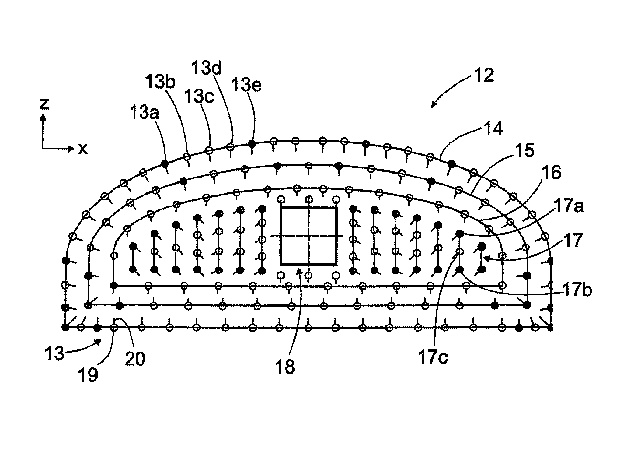
[0053]Typically, a drilling pattern 12 is designed for the drilling of each round, the pattern determining at least the locations of the holes to be drilled and their hole direction angles in the coordinate system of the drilling p...


PUM


Abstract

The invention relates to a method and a software product for designing a drilling pattern for excavating a rock cavern. The invention further relates to a rock-drilling rig, in whose control unit the software product and the method are executable. During designing of the drilling pattern, drill hole bottom locations are placed at a blast plane at the bottom of a round. A drilling pattern design program determines the missing properties of the drill holes viewed from the bottom of the round towards a navigation plane. The program is able to determine a starting location for a drill hole based on the location and the direction of the bottom. The program also performs blasting calculation on the drill holes positioned.

Description

CROSS REFERENCE TO RELATED APPLICATIONS:[0001]This application is the National Stage of International Application No. PCT / FI2007 / 050715, filed Dec. 20, 2007, and claims benefit of Finnish Application No. 20065851, filed Dec. 22, 2006, Finnish Application No. 20065854, filed Dec. 22, 2006, and Finnish Application No. 20075118, filed Feb. 19, 2007.BACKGROUND OF THE INVENTION[0002]The invention relates to a method of designing a drilling pattern for excavating a rock cavern. A drilling pattern determines at least the locations and hole direction angles of drill holes in the coordinate system of the drilling pattern and the lengths of the drill holes for a round to be drilled at a tunnel face. In the method, a designer designs the drilling pattern with the aid of a drilling pattern design program. The object of the invention is described in more detail in the preamble of the first independent claim.[0003]The invention also relates to a software product as claimed in the second independe...

Claims


Application Information

Patent Timeline
Patent Type & Authority Patents(United States)
IPC IPC(8): G06F19/00E21B44/00
CPCE21D9/006F42D3/04F42D1/08E21B44/00G06F30/00
Inventor KESKINEN, MARTTI
Owner SANDVIK MINING & CONSTR OY
Why Eureka
Try Eureka