Tool assembly for evacuating, vacuum testing and charging a fluid system through a bleeder valve

a technology of fluid system and tool assembly, which is applied in the direction of couplings, liquid handling, packaging goods types, etc., can solve the problems of limited space and unsuitable tool assembly for vacuum testing the brake system

Inactive Publication Date: 2009-08-18
PRODN CONTROL UNITS
View PDF24 Cites 4 Cited by
  • Summary
  • Abstract
  • Description
  • Claims
  • Application Information

AI Technical Summary

Benefits of technology

[0003]The present invention is directed to an improved tool assembly for evacuating and charging or pressure filling a hydraulic fluid system having a bleeder valve and which is also adapted for vacuum testing the fluid system for leaks after evacuation of the system. The tool assembly of the invention is also compact so that it may be used with a bleeder valve having limited space around the valve and which also permits the use of a torque wrench when tightening the bleeder valve. In addition, the tool assembly of the invention provides for a positive lock or clamp to the bleeder valve and a positive fluid-tight seal with the fluid system so that the steps of evacuating, vacuum testing and pressure filling of the hydraulic fluid system may be quickly and efficiently performed in succession.

Problems solved by technology

However, the tool assemblies are not suited to vacuum test the brake system for leaks at the end of the evacuation step or pressure fill the brake cylinder with brake fluid since air or hydraulic fluid will leak around the threads connecting the bleeder valve to the brake system.
Furthermore, on some motor vehicles, such as a motorcycle or other recreational vehicles, very limited space is provided for accessing a bleeder valve on a wheel brake cylinder and usually there is no space for rotating the coupler tool to rotate the bleeder valve between its open position and closed position.

Method used


Image

  • Tool assembly for evacuating, vacuum testing and charging a fluid system through a bleeder valve
  • Tool assembly for evacuating, vacuum testing and charging a fluid system through a bleeder valve
  • Tool assembly for evacuating, vacuum testing and charging a fluid system through a bleeder valve

Examples


Embodiment Construction

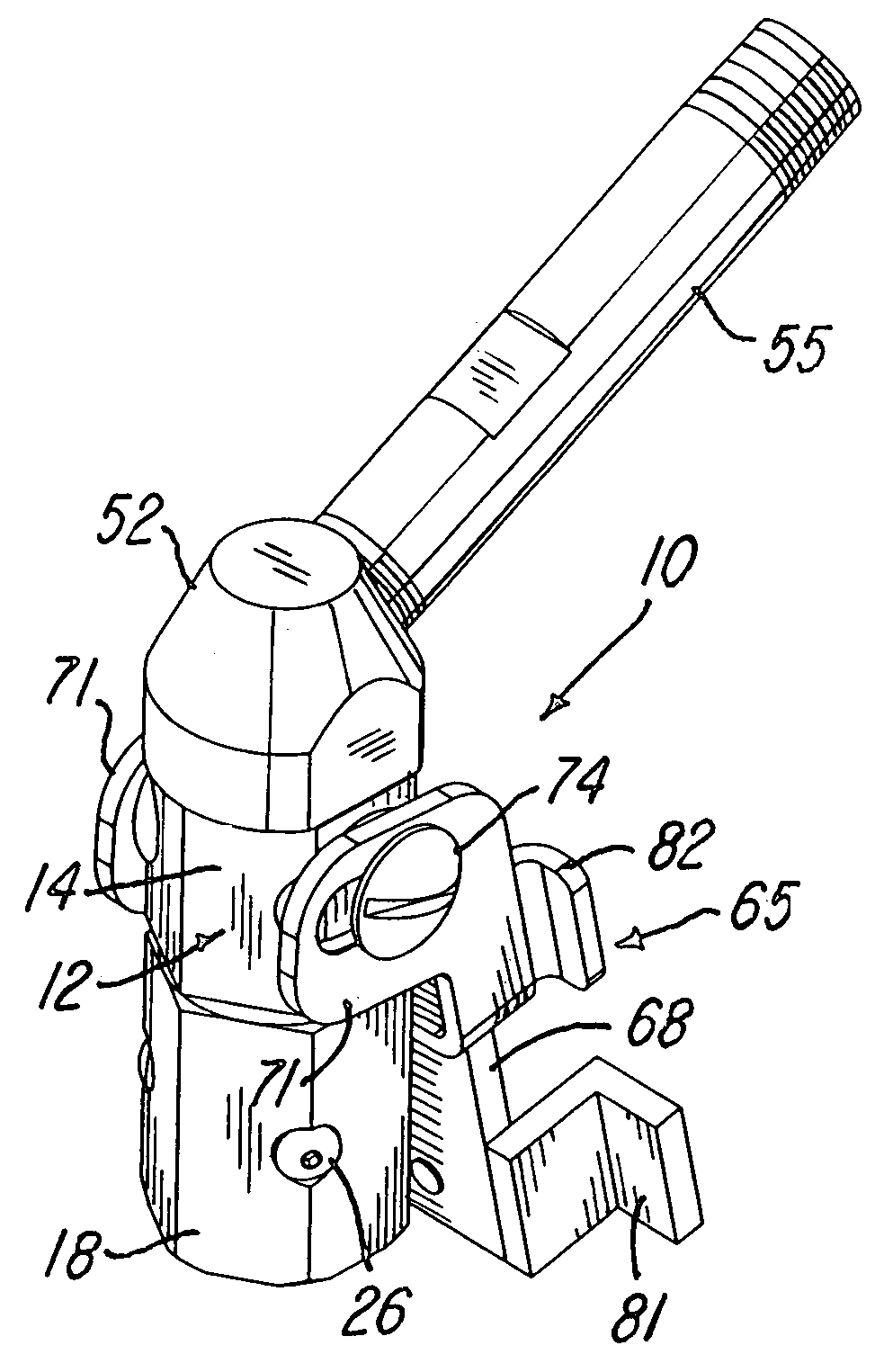
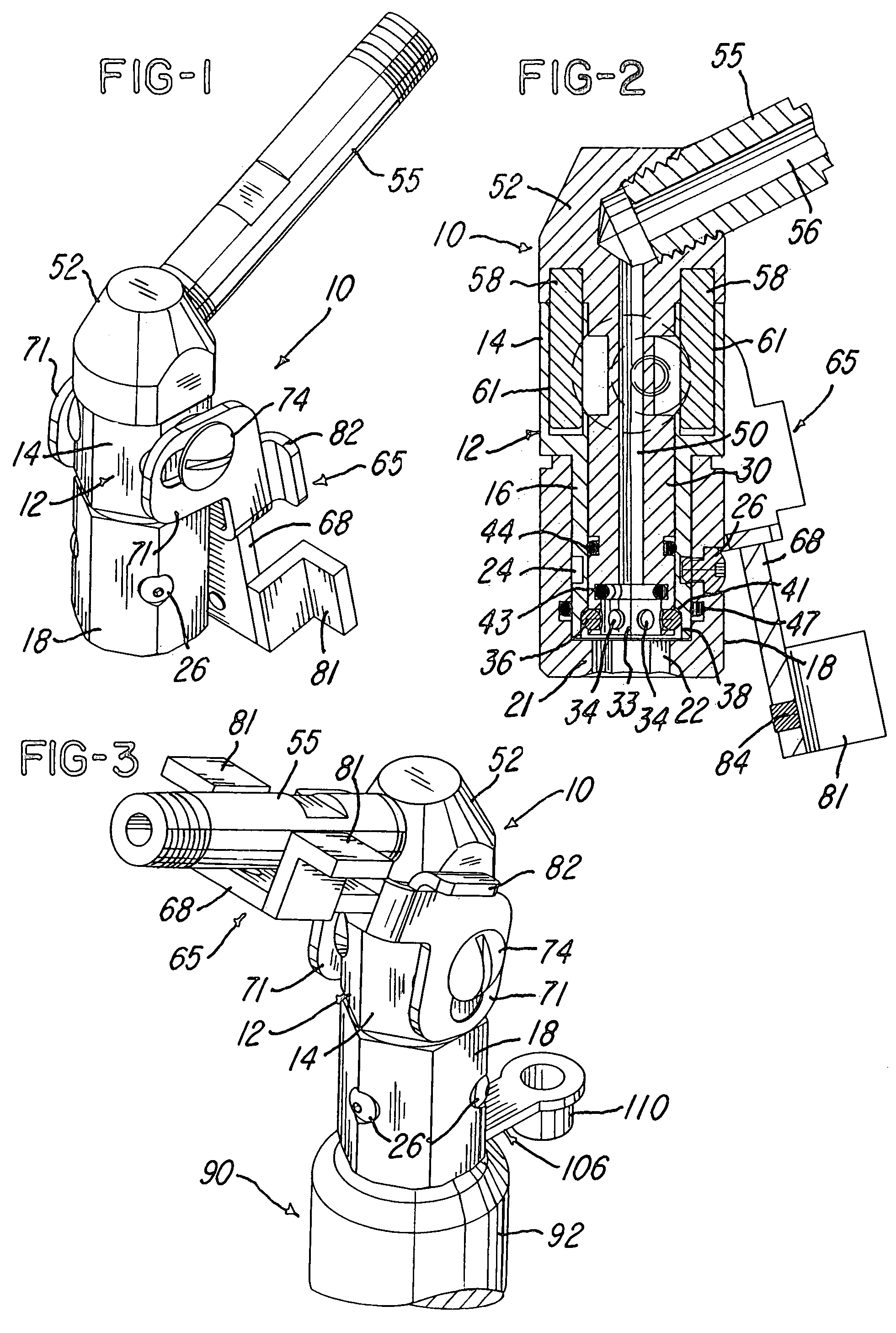
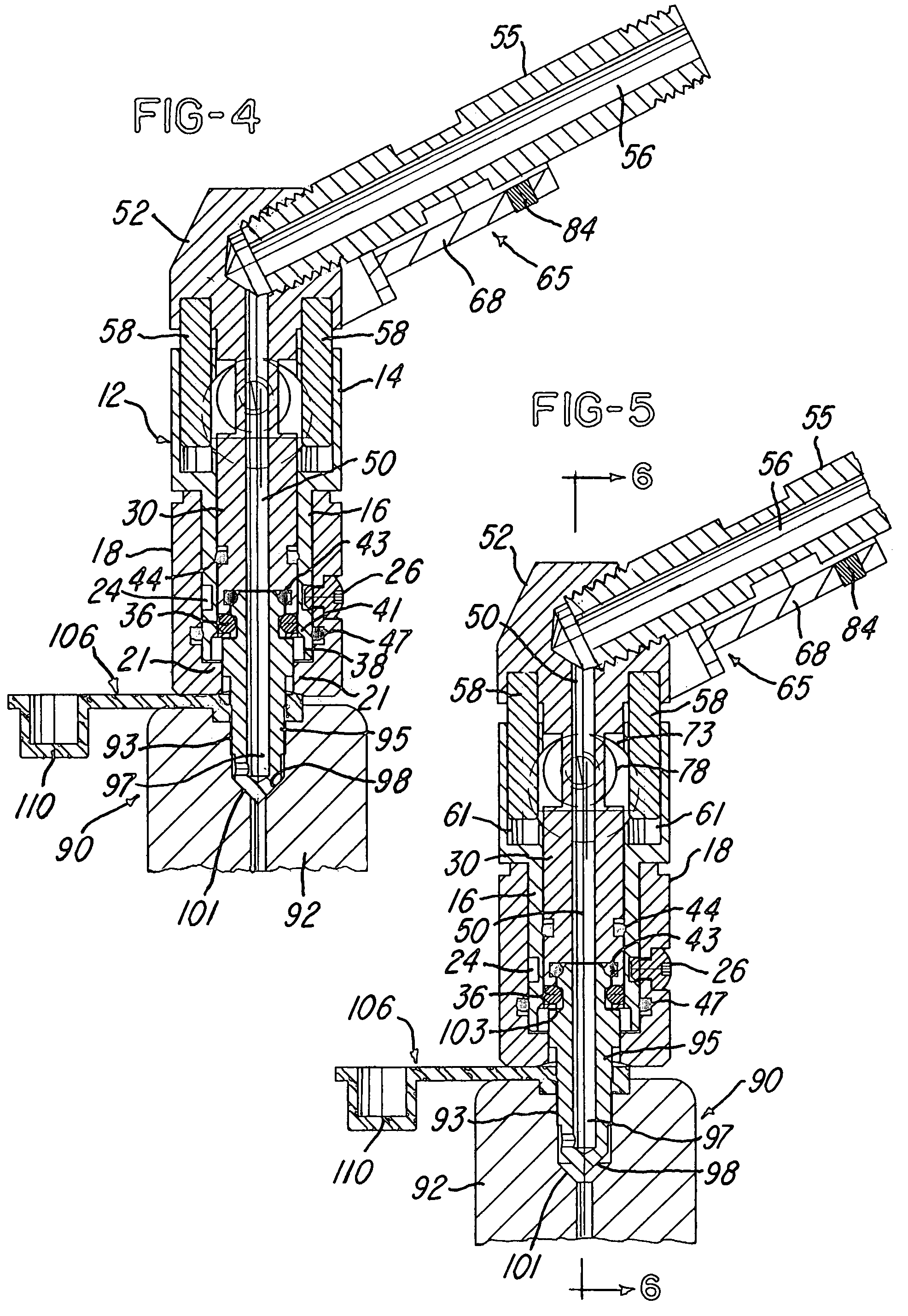
[0013]FIG. 1 illustrates a tool assembly 10 which includes a body 12 having a hexagonal upper portion 14 and a cylindrical tubular portion 16 (FIG. 2) which supports a rotary nut member 18 having a hexagonal outer surface and an inwardly projecting annular flange portion 21 having a hexagonal opening 22. An external groove 24 is formed in the outer surface of the tubular portion 16 of the body 12 and receives a set of three screws 26 threaded into the nut member 18 and having recessed head portions. The screws 26 permit rotation of the nut member 18 on the tubular portion 16 without relative axial movement. An internal tubular member 30 is supported for axial movement within the tubular portion 16 of the body 12 and has an annular lower end portion defining a cylindrical bore or cavity 33. The lower end portion of the tubular member 30 also has six circumferentially spaced holes 34 which receive corresponding spherical balls 36 which project outwardly into a cylindrical bore 38 exte...


PUM

PropertyMeasurementUnit
flexibleaaaaaaaaaa
pressureaaaaaaaaaa
non-rotary aaaaaaaaaa

Abstract

A tool assembly includes a body supporting a rotatable nut which receives and mates with a bleeder valve threaded into a hydraulic fluid system such as a caliper wheel brake or a clutch for a motorcycle. The nut is sealed to the system, and the nut is rotated to move the bleeder valve to an open position while maintaining the seal between the nut and the fluid system. A passage within the body and the nut provides for evacuating the system and then charging fluid into the system. The nut is rotated to move the bleeder valve to its closed position, and the nut is then unclamped and unsealed from the fluid system. In one embodiment, the bleeder valve is gripped to clamp and seal the nut to the fluid system, and in another embodiment, the nut is sealed to the system using a clamping member opposing the nut.

Description

BACKGROUND OF THE INVENTION[0001]The present invention relates to tool assemblies for evacuating and charging fluid systems such as, for example, the tool assemblies disclosed in U.S. Pat. No. 5,560,407, No. 6,257,285, No 6,298,886 and No. 6,799,614 which issued to the assignee of the present invention. These tool assemblies are used for evacuating, vacuum testing and filling or charging a fluid system such as a motor vehicle coolant system or an air conditioning system or a fuel tank system. It is also known to evacuate and fill a motor vehicle hydraulic brake system through the master brake cylinder, for example, as disclosed in U.S. Pat. No. 5,088,529. Air and hydraulic fluid has also been removed from a motor vehicle hydraulic wheel brake cylinder through a bleeder valve projecting from the cylinder and then recharge brake fluid into the brake cylinder through the bleeder valve, for example, as disclosed in U.S. Pat. No. 3,677,513, No. 4,149,560, No. 6,581,905 and No. 7,004,214....

Claims


Application Information

Patent Timeline
Patent Type & Authority Patents(United States)
IPC IPC(8): B60T11/30F16L37/28
CPCF15B21/044Y10T137/87973
Inventor ROBINSON, RANDY S.
Owner PRODN CONTROL UNITS
Why Eureka
Try Eureka