Electrically safe receptacle

a technology of electric wall receptacles and receptacles, which is applied in the direction of coupling device details, coupling device connections, coupling protective earth/shielding arrangements, etc., can solve the problems of mechanical slide wear and tear, increase complexity, and undermine reliability, so as to reduce the time for the switch and facilitate replacement

Inactive Publication Date: 2009-08-18
FERGUSON THOMAS WILMER +1
View PDF48 Cites 38 Cited by
  • Summary
  • Abstract
  • Description
  • Claims
  • Application Information

AI Technical Summary

Benefits of technology

[0043]In one preferred embodiment of this invention the receptacle in its normal unused state would be connected to the electrical power circuit through a relay that is normally open. The relay is controlled by a strategically placed sensor on the face of the receptacle situated in the general area that lies between the two vertical openings. The sensor may be any of a range of sensors such as infrared, capacitive proximity, heat or light detecting, or the newer smart sensors that have the capability of additional functions beyond the normal sensing capabilities. With 120 vac applied to one side of the normally open relays, and the sensor controlling the return path, the receptacle is electrically safe, that is no current is flowing, until the sensor detects a cooperating male plug being inserted into the receptacle. If the sensor is not completely covered, or in the case of a heat detecting sensor detects a temperature in excess of the ambient temperature, the relay remains open and will not conduct electricity. If the sensor detects the insertion of a cooperating male plug with no deviation of the temperature set point, it will energize the coils that control the relays causing them to close and allow for the flow of electrical current. Using sensors and relay switches reduces the time for the switches to close to the area of microseconds. It is the fast closing time of the relays that prevents arcing and the subsequent degradation of the relay contacts. The additional advantage of using relays mounted on the back of the receptacle is the ease of replacement in the event of failure. Simply remove the old relay from its socket and plug in a new one.
[0046]It is a further object of this invention to provide an electrically safe receptacle having normally open switched power circuits to reduce and prevent accidental electrocution resulting from insertion of conductive foreign elements into the receptacle.

Problems solved by technology

The multiple task which it is designed to undertake add to the complexity and undermines the reliability.
Insertion of a conductive object into one female element will close the switch to energize the opposite female element prior to contact of the male plug conductive elements with the female conductive elements this arrangement is designed to reduce arcing at the contacts and at the face of the outlet but does not completely eliminate the arc hazard.
There are several problems with the Barkas device that make it impractical.
The mechanical slide is subject to wear and tear due to the repeated insertion of either a male plug or conductive device.
The mechanical slide also closes the contactors by mechanical force, which is slow enough to cause internal arcing at the contactors, and thereby may require frequent replacement of expensive parts.
Normal usage of the Sperrazza device reveals a timing problem with regard to the closure of the switch contacts.
This solved the problem of face arcing, but the relative slowness of the mechanical closure operation permits arcing at the switch contacts and the subsequent degradation.
A second defect of the Sperrazza device is the preclusion of variable plug blade orientation designs.
Sperrazza permits insertion of only non-polarized two prong male plugs, and excludes all other male plug designs such as the three prong grounded plug or two prong polarized plug designs thereby limiting it's usefulness.
In addition, Sperrazza uses a long narrow spring device as part of the current carrying elements within the circuit, which not only occupies considerable space, but also generates heat within the device.
Any combination of activated switches other than all four switches would result in a failure to energize the female conductive elements.
The use of slides, springs, levers, cams, and springs are all valid, but limited in the effectiveness of their intended function.
Specifically, the critical strength of all these mechanical devices is also their critical weakness.
Finally, degradation of the mechanical means used is another inherent weakness of all the previously referenced mechanical devices.

Method used


Image

  • Electrically safe receptacle
  • Electrically safe receptacle
  • Electrically safe receptacle

Examples


Embodiment Construction

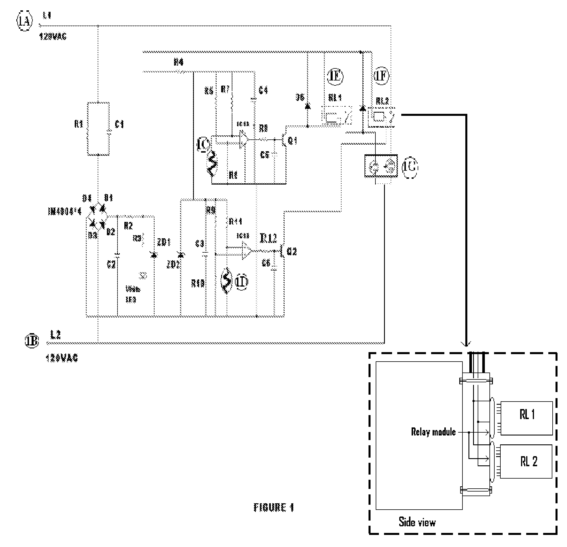
[0051]FIG. 1 shows the 120 VAC connection 1A is applied to one side of 1E and 1F the normally open independent switches and controlled by activation of the corresponding coil associated with each switch. 1A is also connected to one side of the corresponding coils of 1E and 1F. Insertion of a proper male corresponding plug into 1G will activate sensor 1C. When sensor 1C is activated, a return path is provided for the coil on 1E. When the coil on 1E is energized, it pulls closed the corresponding switch energizing the conductive female elements on one side of plug 1G allowing the electrical appliance to operate. Removal of the corresponding male plug deenergizes sensor 1C which removes the return path for coil 1E allowing the corresponding switch to open and remove electrical current from the female elements of plug 1G.

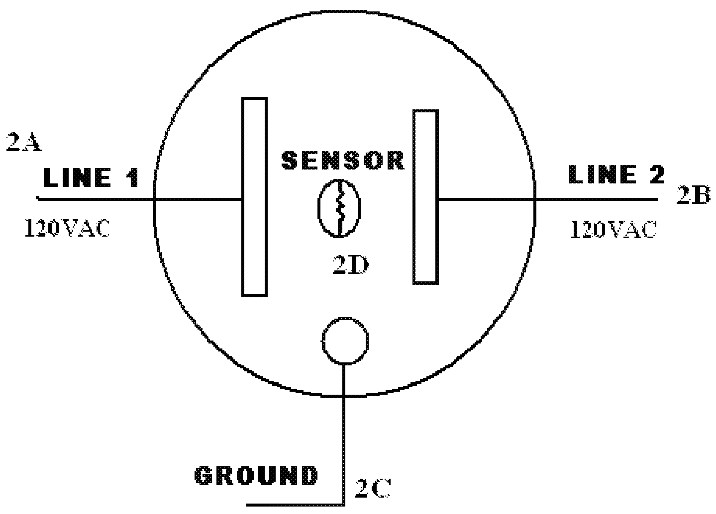
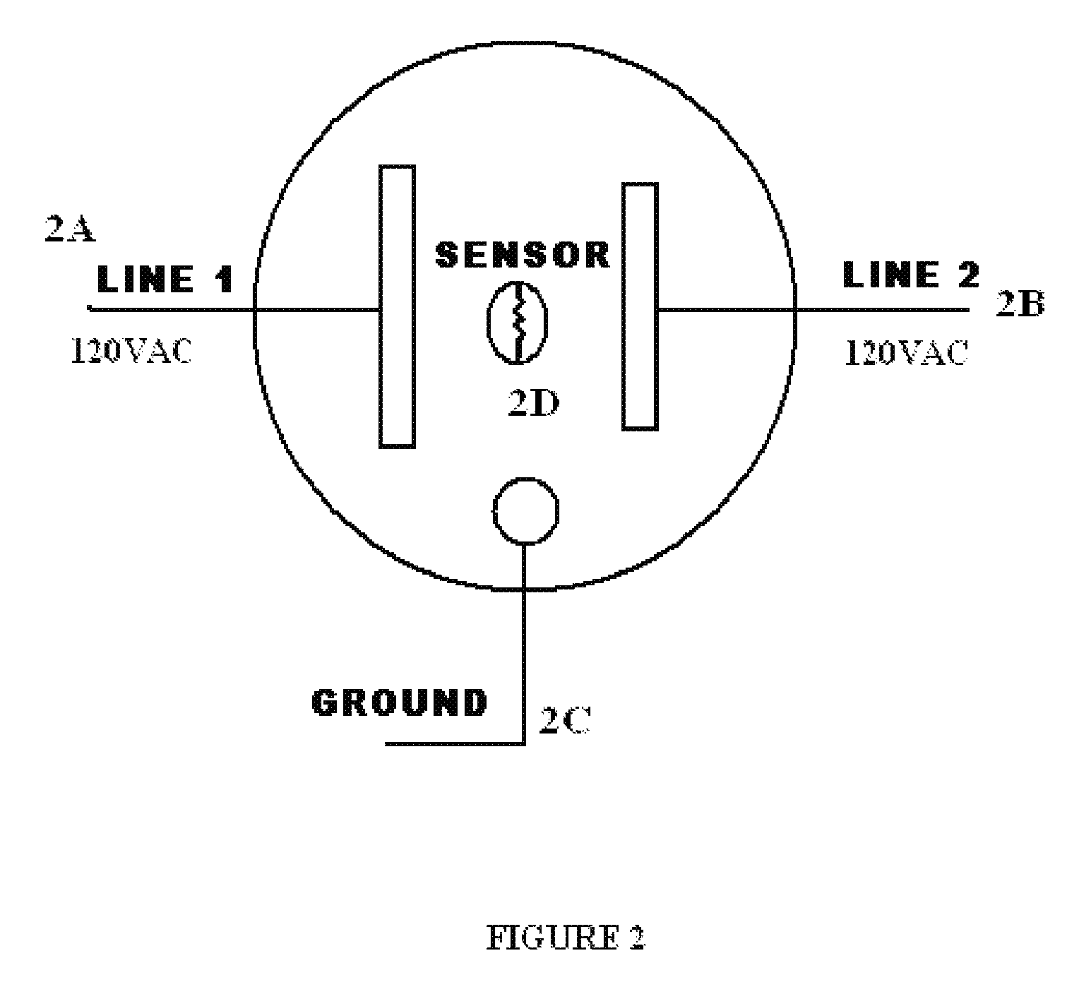
[0052]FIG. 2 shows face of a sensor equipped electrically safe receptacle in one preferred embodiment of this invention. 2A is the longer hot element configured in an i...


PUM


Abstract

An electrically safe receptacle that in it's normal quiescent state will not have electrical current flow. Said electrically safe receptacle will be equipped with normally-open switches on one or both female conductors that are controlled by a strategically placed sensor to detect the insertion of a male plug. Detection of the male plug insertion will signal the normally open switches to close the circuit pathway and allow for the flow of electrical current to the device permitting normal operation. Insertion of a foreign conductive device such as a hair pin, knife blade, or metallic tool in one or both female conductors will fail to activate the sensor and thereby reduce or eliminate the possibility of accidental electrocution by preventing the flow of electrical current.

Description

FIELD OF INVENTION[0001]In general, this invention relates to electrical wall receptacles. Specifically to wall receptacles designed to reduce or eliminate the possibility of injury by accidental electrocution or shock.[0002]It has been known for many years that electric current is useful and necessary for the operation of many work-saving appliances, and equipment we use everyday. It has also been known for many years that the same characteristics that make electric current useful may—under certain conditions—make it a significant hazard capable of causing injury or death.[0003]In recognition of this hazard, OSHA has established annual safety training requirements for individuals who install or repair and maintain electrical equipment in an industrial environment. These individuals must undergo annual safety training, and the equipment and devices they install must comply with the National Electrical Code.[0004]While professional electricians may be trained to handle electricity wi...

Claims


Application Information

Patent Timeline
Patent Type & Authority Patents(United States)
IPC IPC(8): H01R3/00
CPCH01R13/44H01R13/652H01R13/665H01R13/7038H01R24/78H01R2103/00H01R13/6683Y10S439/955
Inventor FERGUSON, THOMAS WILMERVEITH, GREGORY W.
Owner FERGUSON THOMAS WILMER
Why Eureka
Try Eureka