Apparatus for changing bits of machine tool

a technology for changing bits and machine tools, applied in the field of machine tools, can solve problems such as the need for precise operation of a complicated mechanism, and achieve the effect of simple and durabl

Inactive Publication Date: 2009-08-18
SUN YING +1
View PDF8 Cites 8 Cited by
  • Summary
  • Abstract
  • Description
  • Claims
  • Application Information

AI Technical Summary

Benefits of technology

[0006]It is the primary objective of the present invention to provide a simple and durable bit-changing apparatus for use in a machine tool.

Problems solved by technology

This requires precise operation of a complicated mechanism.

Method used


Image

  • Apparatus for changing bits of machine tool
  • Apparatus for changing bits of machine tool
  • Apparatus for changing bits of machine tool

Examples


Embodiment Construction

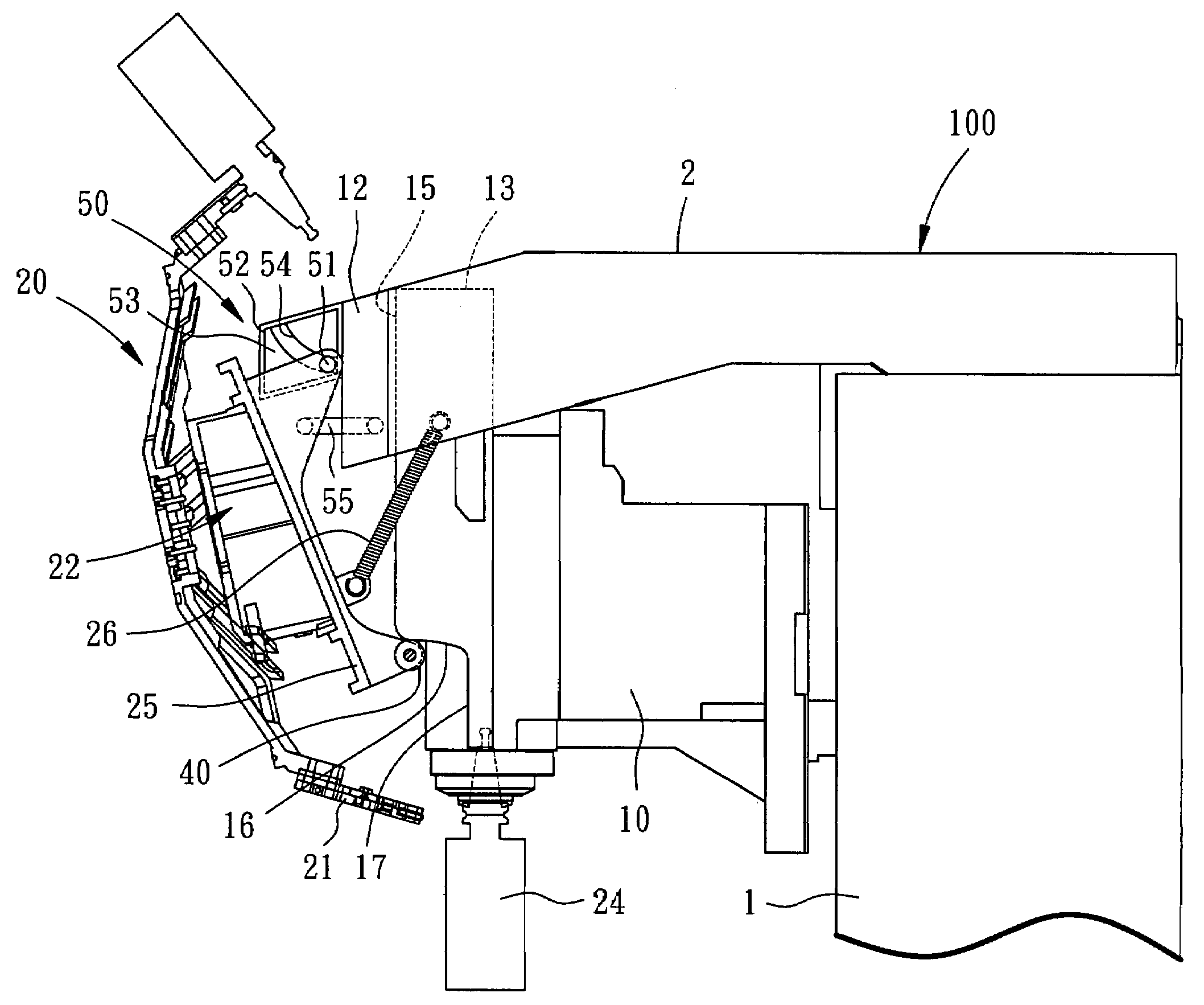
[0016]Referring to FIGS. 3 through 7, a machine tool is equipped with a bit-changing apparatus according to the preferred embodiment of the present invention. The machine tool includes a post 1, a beam 2 connected to the post 1, a supporting element 12 attached to the beam 2 and a bit-driving unit 10 vertically movable thereon. The bit-changing unit is used to carry and change holders 24 for holding bits so that a selected one of the bits can be engaged with the bit-driving unit 10.

[0017]The bit-changing unit includes a cam 13 attached to the bit-driving unit 10, a linkage 50 connected to the supporting element 12, a rocker 25 connected to the linkage 50 and a disc 20 rotationally connected to the rocker 25. A reduction device 22 is connected to the disc 20 so that the disc 20 is operated at a low speed. The cam 13 is formed with an upper rectilinear section 15, a lower rectilinear section 17 and a curved section 16 between the upper rectilinear section 15 and the lower rectilinear ...


PUM


Abstract

A machine tool is provided with a bit-changing apparatus including a cam, a rocker, a roller, a linkage, a pulling element, a disc and clips. The cam is attached to the machine tool. The roller is attached to the rocker and movable against the cam. The linkage includes at least one track attached to the machine tool, a sliding element attached to another end of the rocker and movable on the track, and a connecting rod formed with an end pivotally connected to the machine tool and another end pivotally connected to the rocker. The pulling element is provided between the rocker and the machine tool so that the roller is kept against the cam. The disc is rotationally supported on the rocker. Each of the clips is attached to the disc and used to clip a holder for holding a bit so that a selected bit can be engaged with a bit-driving unit of the machine tool.

Description

FIELD OF INVENTION[0001]The present invention relates to a machine tool and, more particularly, to an apparatus for changing bits of a machine tool.BACKGROUND OF INVENTION[0002]Referring to FIG. 1, a conventional machine tool includes a bit-driving unit 10 and a bit-changing unit. The bit-changing unit is used to carry and change holders 24 for holding bits so that a selected one of the bits is engaged with the bit-driving unit 10. The conventional machine tool includes a beam 2 formed thereon, a supporting element 12 connected to the beam 2 and a pinion 11 provided thereon. The bit-changing unit includes a rocker 25 connected to the supporting element 12 with a pivot 14 and a disc 20 rotationally connected to the rocker 25. A gear 23 is engaged with the pinion 11 and a reduction device 22 is provided between the disc 20 and the gear 23 so that the disc 20 is operated at a low speed as the pinion 11 is operated at a high speed. A roller 18 is supported on the rocker 25 and movable a...

Claims


Application Information

Patent Timeline
Patent Type & Authority Patents(United States)
IPC IPC(8): B23Q3/157
CPCB23Q3/15706B23Q5/347Y10T483/1755Y10T483/1795Y10S483/90B23Q3/15534
Inventor SUN, YINGSUN, CHI
Owner SUN YING
Why Eureka
Try Eureka