Top down trap lock shingle system for roofs

a trap lock and roof technology, applied in the field of protective and aesthetic roofing shingles, to achieve the effect of preventing water intrusion and more structural durability

Inactive Publication Date: 2009-08-25
TOP DOWN SIDING
View PDF16 Cites 33 Cited by
  • Summary
  • Abstract
  • Description
  • Claims
  • Application Information

AI Technical Summary

Benefits of technology

[0007]A shingle comprising a base layer, an intermediate layer spaced and strategically joined by adhesive to an upper portion of said base layer and a top layer that extends from the base of the intermediate layer well beyond the top of the intermediate layer. The bottom layer has an extended strategically sized area or zone for applying fasteners such as nails or staples along its lower base edge. The shingle has a trap lock recess area that receives the top edge portion of an adjacent lower shingle. Thus, a lower shingle has a top layer for securing the lower shingle to the shingle above. Each shingle includes additional adhesive areas for securely fastening rows of shingles in a top down procedure to the roof surface. By trap locking adjacent rows of shingles, the shingle system has more structural durability and integrity against wind damage to prevent water intrusion.
[0009]One of the important features of the present shingle system is its dramatic increased resistance to wind uplift. The present system also is believed to reduce the number of fasteners required and can also increase the reveal from certain standard areas to larger areas allowing a roof to be covered more quickly, reducing installation time.
[0014]It is another object of this invention to increase shingle durability inspite of high winds, reduce the number of fasteners, and increase the reveal to a larger area allowing the roof to be covered more quickly reducing installation time.

Problems solved by technology

But the bottom portion of the intermediate layer is not fastened to the base layer to allow a trap lock recess area that has sufficient space for receiving the top layer of a shingle positioned below this specific shingle.

Method used


Image

  • Top down trap lock shingle system for roofs
  • Top down trap lock shingle system for roofs
  • Top down trap lock shingle system for roofs

Examples


Embodiment Construction

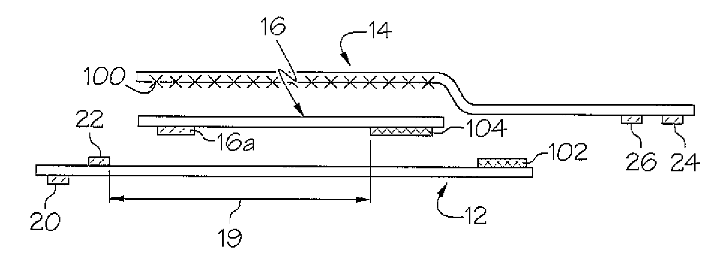
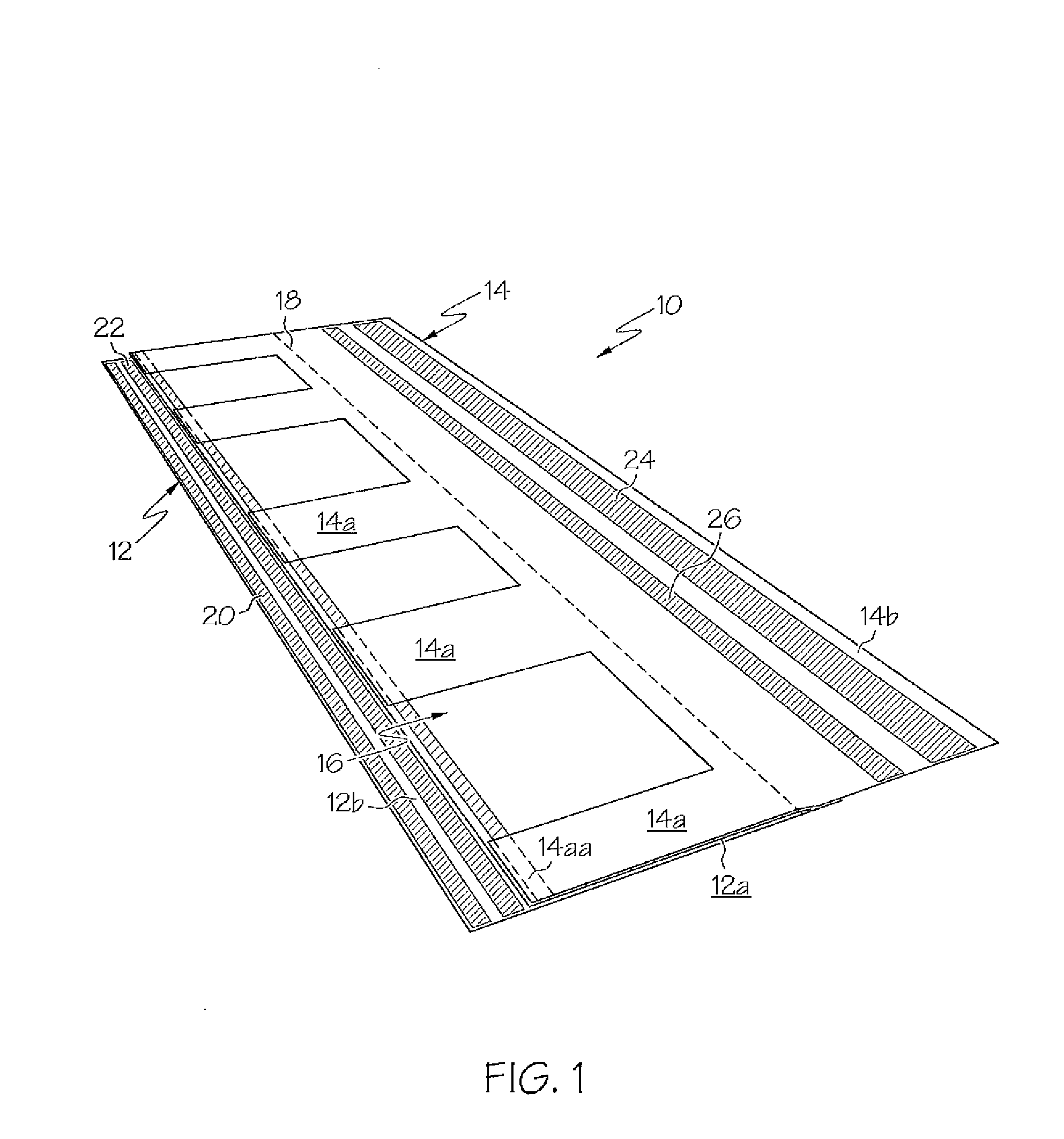
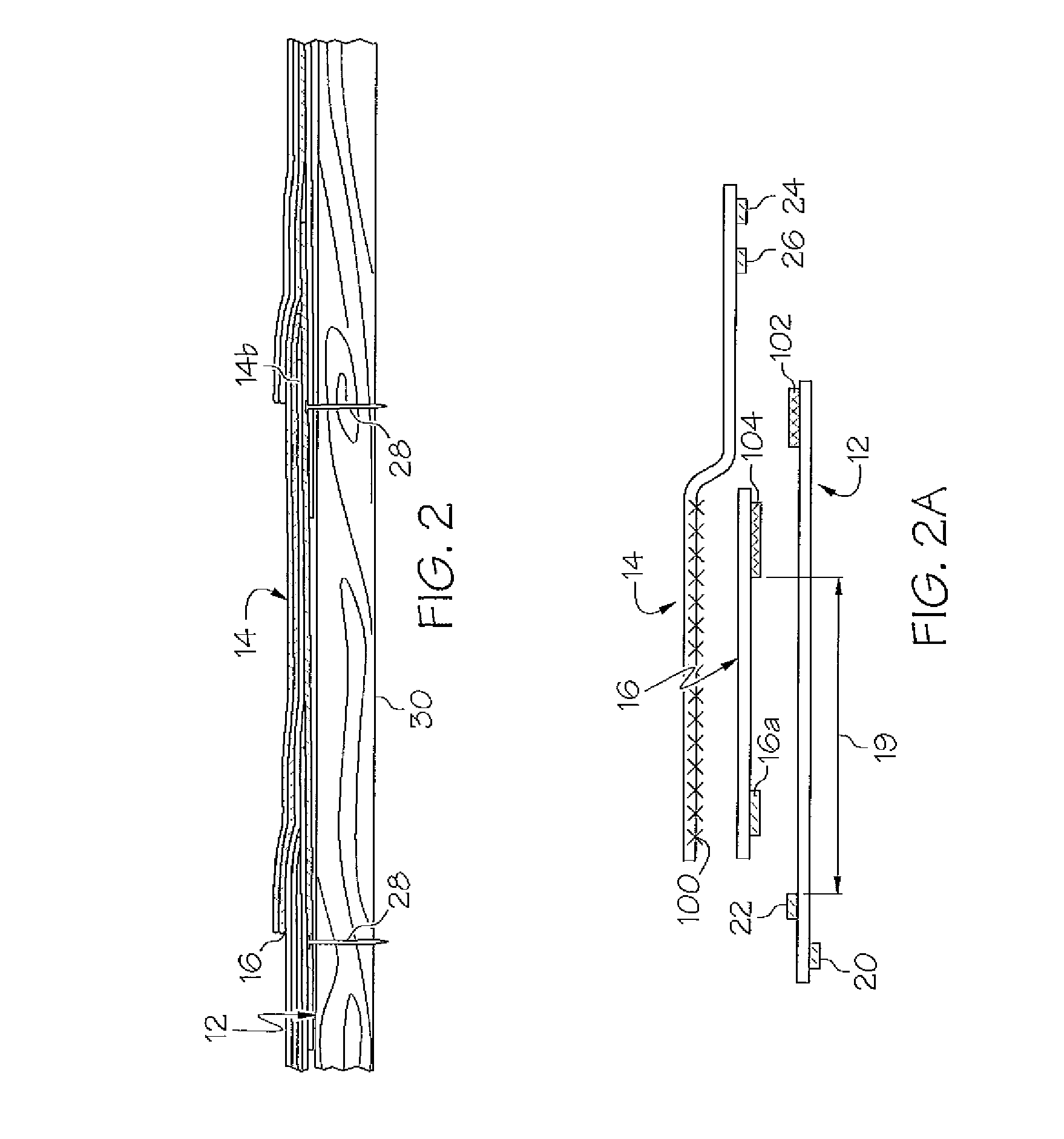
[0022]Referring now to the drawings and, in particular, FIG. 1 and FIG. 2, a shingle in accordance with the present invention is shown. The shingle 10 is made of asphalt, fiberglass, a composite material or any combination thereof and is comprised of three separate, relatively thin, somewhat flexible, layers formed in a laminate and glued together or heat sealed together as described herein. The shingle 10 is comprised of three layers of material 12, 14 and 16. Layer 12 is the base or bottom layer and has sections 12a and 12b which represent different areas on layer 12. Area 12b represents an attachment flange or hem that is used for fastening the shingle to a wooden roof. Layers 14 and 16 do not extend along the base over area 12b of the lower shingle area. Note that shingle area 12b section also has adhesive band 20 on its underside and an adhesive band 22 on its topside. Adhesive bands and dimensions in this embodiment are shown but not limited to just these areas. Other embodime...


PUM


Abstract

A top down trap lock shingle system that includes a plurality of identical shingles, each shingle having a bottom layer, an intermediate layer permanently attached to the bottom layer along the intermediate layer top edge forming a pocket between the bottom layer and the intermediate layer and a top layer permanently attached to said intermediate layer and permanently attached to said top edge of said bottom layer forming an extended tab along the top of the shingle that includes strips of adhesive and said bottom layer having an enlarged nailing or stapling zone that extends beyond the bottom edge of the intermediate layer, said attachment flange including a top adhesive layer and a bottom adhesive layer. The shingles are trapped and locked by inserting the top tab portion of the top area in a top down manner onto an above shingle row staggered to protect the seams and fastening the bottom edge of the shingle to the plywood roof thus trap locking each of the shingle rows in place. The laminated shingle system is especially durable and protectful against high winds preventing wind damage and water intrusion.

Description

BACKGROUND OF THE INVENTION[0001]1. Field of the Invention[0002]This invention relates generally to protective and aesthetic roofing shingles that cover the roof of a building and, specifically, to a laminated roofing shingle that is durable in high winds and heavy rains. Each shingle has a top insert area and a bottom edge trap lock recess area that receives the top insert area of a lower shingle. The shingles are installed in rows from the top of a roof peak in a downward direction.[0003]2. Description of Related Art[0004]Shingles are known in the art and are made from asphalt, fiberglass, a composite material or any combination thereof roofing materials. The shingles are typically attached to the roof starting from the bottom of the roof edge. The shingles are fastened to the roof in rows with the next row overlapping the lower row. The shingles are secured to the roof typically with nails or staples. Also, adhesives may be used in various areas in the shingle construction. Many ...

Claims


Application Information

Patent Timeline
Patent Type & Authority Patents(United States)
IPC IPC(8): E04D11/02
CPCE04D1/26E04D1/34Y10T428/24752E04D2001/3435
Inventor SWANSON, LIEF ERIC
Owner TOP DOWN SIDING
Why Eureka
Try Eureka