Wave power installation

a technology for installing wave power and power, applied in the direction of couplings, electric generator control, fluid couplings, etc., can solve the problems of reducing the efficiency of vacuum creation, requiring significant capital expenditure for its construction, and reducing the reliability of its operation, so as to increase the output efficiency and power of the wave power installation

Active Publication Date: 2009-08-25
LYATKHER VICTOR
View PDF6 Cites 2 Cited by
  • Summary
  • Abstract
  • Description
  • Claims
  • Application Information

AI Technical Summary

Benefits of technology

[0005]The present invention is dedicated to solving a problem of creation of a structurally simple wave power installation with a possibly minimal number of movable elements. The invention enables achieving a simple and efficient design of water wave power installations, increasing their power and reliability by means of creating vacuum independently on the movement direction of ejector units incorporated therein.
[0009]During research, it has been established that vacuum can be created in the cavity of the float independent on the direction of reciprocal-progressive movement of the confuser-diffuser conduit. It has been achieved because the ejector unit is disposed in water under the float having the cavity accumulating air, and is performed as a confuser-diffuser conduit, which conduit in its minimal cross-section is communicated via at least one reverse valve with the cavity. As a result, a predetermined extent of vacuum (air rarefaction) is created during the upward motion of the conduit, fixed to the float, following water waves, as well as during the downward motion thereof. Thus, the rarefaction in the cavity practically continuously takes place that allows increasing the output efficiency and power of the wave power installation.

Problems solved by technology

Such power station has many movable elements that reduces reliability of its operation and requires significant capital expenses for its construction.
However, the absence of a contraction and expansion conduit of a suitable profile, which would allow creating vacuum independent on the direction of its movement, reduces the efficiency of vacuum creation, and leads to decreasing productivity of the suction grating and the entire wave power installation.

Method used


Image

  • Wave power installation
  • Wave power installation

Examples


Embodiment Construction

[0012]While the invention may be susceptible to embodiment in different forms, there is shown in the drawing, and will be described in detail herein, a specific embodiment of the present invention, with the understanding that the present disclosure is to be considered an exemplification of the principles of the invention, and is not intended to limit the invention to that as illustrated and described herein.

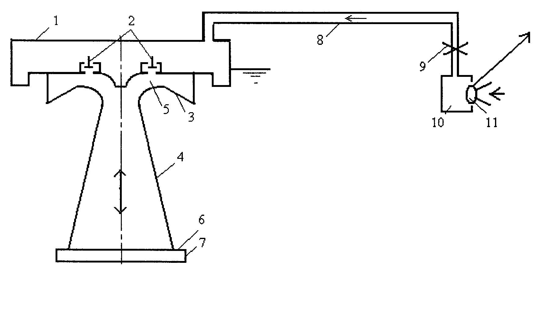
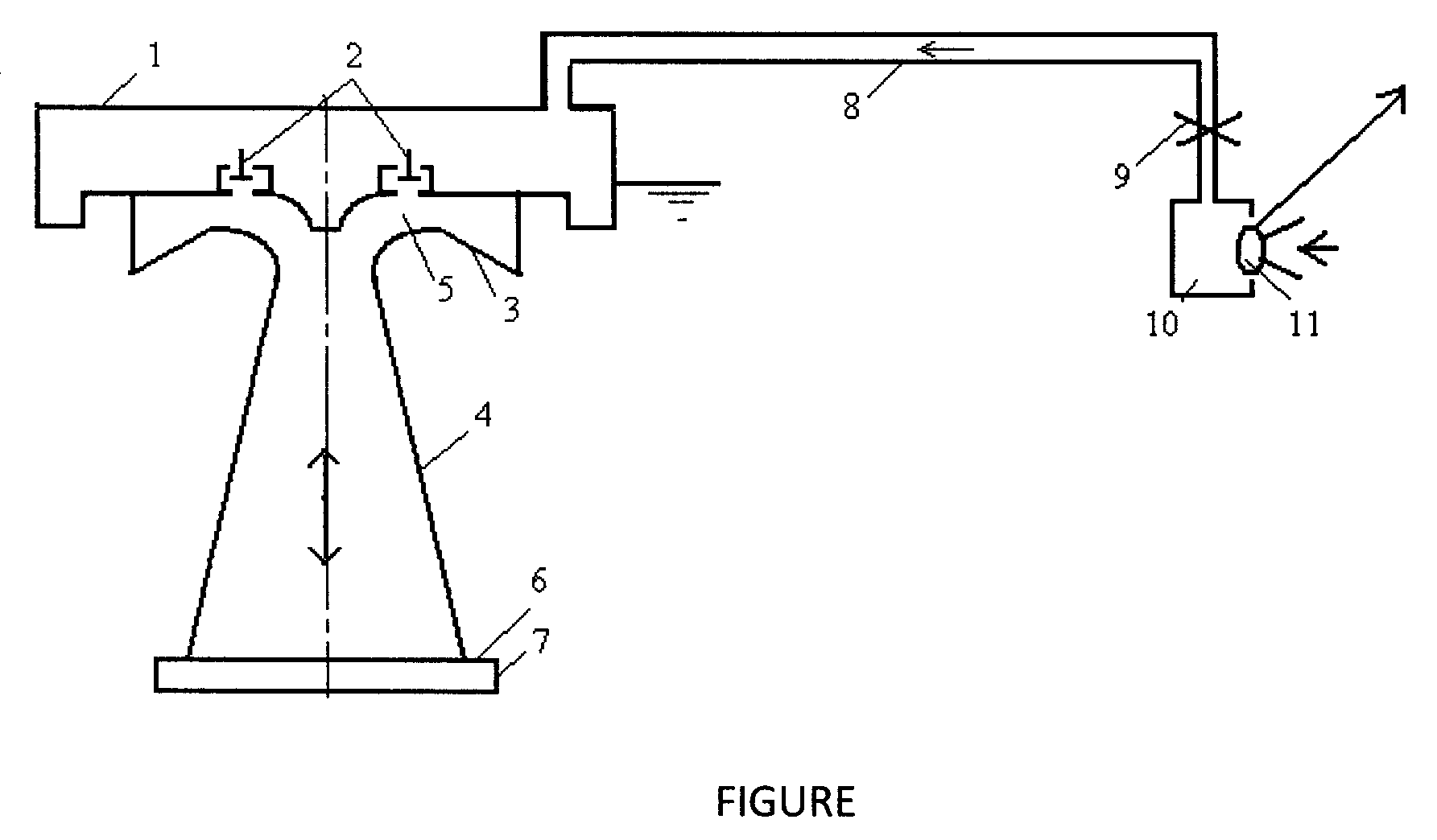
[0013]As illustrated on FIGURE, the wave power installation comprises a float (1) with a cavity made herein capable of accumulating air and at least one reverse valve (2). The installation comprises an ejector unit fixed to the float 1 on its underside, and disposed in water. The ejector unit is performed as a confuser-diffuser conduit consisting of two channels: an upper channel (3) and a lower channel (4), communicated with each other in the vicinity of their least flow cross-section (5). The upper channel 3 is located under the bottom of float 1 and is narrowed in a direction ...


PUM

PropertyMeasurementUnit
areaaaaaaaaaaa
poweraaaaaaaaaa
pressureaaaaaaaaaa

Abstract

A wave power installation is presented, comprising a flow chamber, an air-driven turbine disposed in the chamber and coupled with an electro-generator, a float having a cavity accumulating air, communicated with the chamber, a vacuum-creating ejector disposed in water mounted under the float, which ejector is performed as a confuser-diffuser conduit, wherein at least a portion thereof is vertically positioned. The conduit has a minimal through cross-section. At least one reverse valve is mounted in the vicinity of the minimal cross-section. The conduit is communicated with the cavity via the reverse valve. The chamber and turbine can be located on a coast. In embodiments, the conduit is furnished with a cylindrical nozzle, thereby making it stepwise widening downwardly. During both the upward and downward motions of the float, airflow is produced through the chamber, providing for practically continuous generation of electric energy by the installation, and improving its efficiency.

Description

CROSS-REFERENCE TO RELATED APPLICATIONS[0001]This U.S. patent application claims priority under 35 U.S.C. 119 (a) through (d) from a Russian Federation patent application No. 2007135134 filed on 21 Sep. 2007.BACKGROUND OF THE INVENTION[0002]The invention relates to the field of hydro-power engineering and is intended for production of electric power based on the utilization of renewable energy of surface waves of ocean, sea, lakes, and other similar water reservoirs.[0003]There is known a water-wave power plant comprising an immovable vertical pipe, whose lower half is submerged into water, a movable pipe enclosing the immovable pipe and supplied with a float, a turbine situated below the water level coupled to an electro-generator and rigidly attached to the movable pipe (U.S. Pat. No. 4,914,915, issued 10 Apr. 1990). Such power station has many movable elements that reduces reliability of its operation and requires significant capital expenses for its construction.[0004]The closes...

Claims


Application Information

Patent Timeline
Patent Type & Authority Patents(United States)
IPC IPC(8): F16D31/02F03B13/12
CPCF03B13/24Y10T29/5172Y02E10/38Y02E10/30
Inventor LYATKHER, VICTOR
Owner LYATKHER VICTOR
Why Eureka
Try Eureka