Method for cooling a fuel cell

a fuel cell and cooling technology, applied in the field of fuel cell cooling, can solve the problems of generating a certain quantity of waste heat, prone to errors, critical, costly, etc., and achieve the effect of simple and efficient means and secure and reliable operation of the fuel cell

Active Publication Date: 2018-04-10
CELLCENTRIC GMBH & CO KG
View PDF7 Cites 2 Cited by
  • Summary
  • Abstract
  • Description
  • Claims
  • Application Information

AI Technical Summary

Benefits of technology

[0004]The object of the present invention is to provide a method for cooling a fuel cell which avoids these disadvantages, and which allows secure and

Problems solved by technology

In addition to electrical power and product water, the fuel cells also always generate a certain quantity of waste heat which is undesirable, and which according to the general prior art is discharged from the area of the fuel cell via a liquid cooling medium.
In particular when the fuel cells are operated with hydrogen, gas leaks within the fuel cell and the fuel cell system are a significant safety hazard, since ignitable or even explosive mixtures may result from hydrogen and the oxygen in the ambient air.
This is critical, costly, an

Method used


Image

  • Method for cooling a fuel cell
  • Method for cooling a fuel cell

Examples


Embodiment Construction

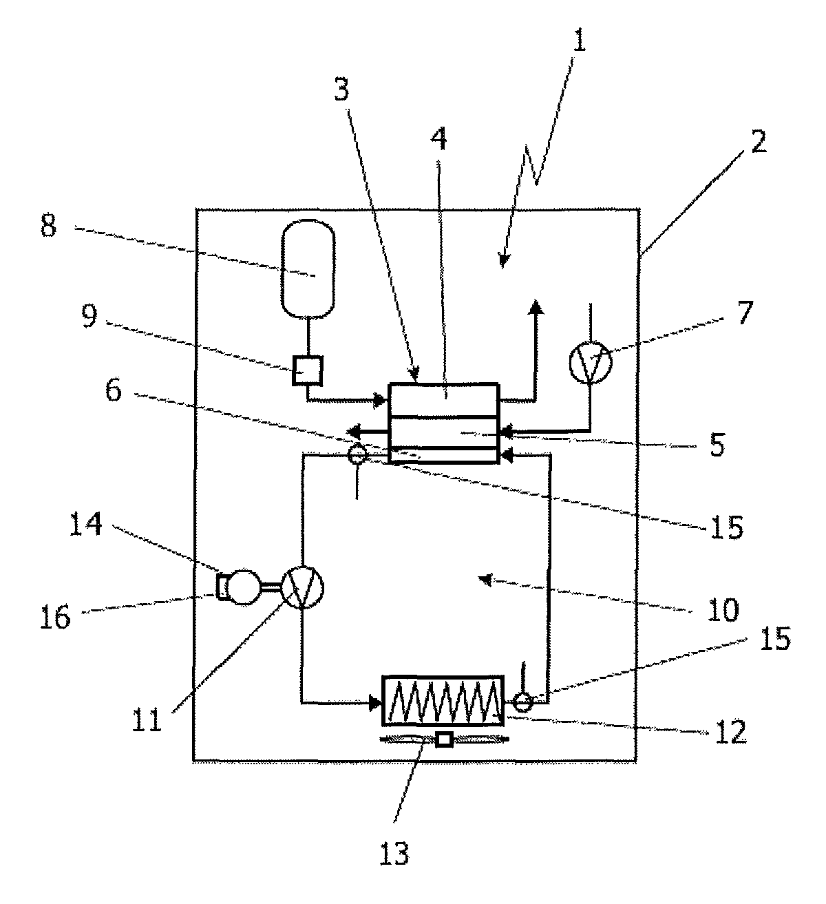
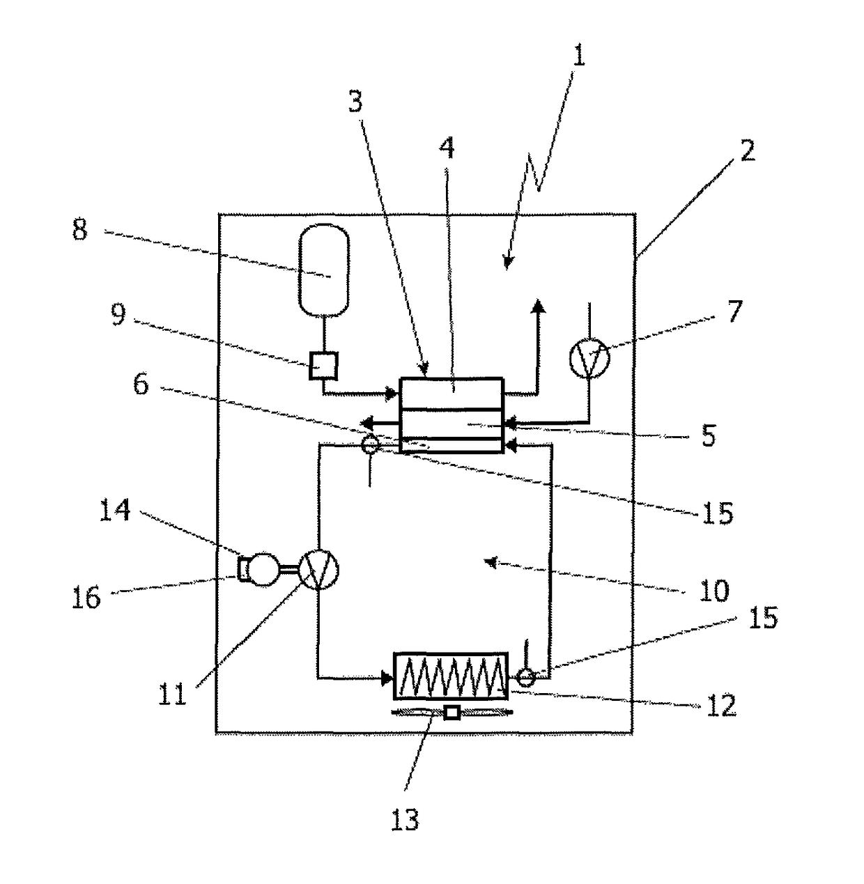
[0014]A fuel cell system 1 in a highly schematic illustration is apparent in the single appended FIGURE. The fuel cell system 1 is intended for installation in an indicated vehicle 2. The core of the fuel cell system 1 is a fuel cell 3, which by way of example is designed as a PEM fuel cell. In its interior the fuel cell 3 essentially has three separate chambers, which in the customary design are in each case implemented as single cells which are then stacked to form a fuel cell stack, a so-called stack. The individual chambers of the single cells of the fuel cell stack 3 are then connected to one another via corresponding line elements or collectors. The chambers illustrated in the FIGURE, using the example of a single cell, are an anode chamber 4, a cathode chamber 5, and a chamber 6 through which a liquid cooling medium flows and which could also be referred to as a cooling heat exchanger. In a manner known as such, the cathode chamber 5 is supplied via an air conveying device 7 ...


PUM


Abstract

A method for cooling a fuel cell (3) using a liquid cooling medium, wherein of the starting materials supplied to the fuel cell and the products discharged from the fuel cell, at least one is gaseous during at least one of the operating conditions. The cooling medium is conveyed through the fuel cell (3) by a coolant conveying device (11). The power consumption of the coolant conveying device (11) is compared to predefined reference values in order to detect gas in the liquid cooling medium by a deviation of the power consumption from the predefined reference values.

Description

BACKGROUND OF THE INVENTIONField of the Invention[0001]The invention relates to a method for cooling a fuel cell using a liquid cooling medium, in which the starting materials supplied to the fuel cell and the products discharged from the fuel cell, at least one is gaseous during at least one of the operating conditions, and the cooling medium is conveyed through the fuel cell by a coolant conveying device.Description of Related Art[0002]Fuel cell systems are known from the general prior art. For generating electrical power, these systems use fuel cells, which may be designed as PEM fuel cells, for example. In addition to electrical power and product water, the fuel cells also always generate a certain quantity of waste heat which is undesirable, and which according to the general prior art is discharged from the area of the fuel cell via a liquid cooling medium. The liquid cooling medium is typically conveyed in a cooling circuit by at least one coolant conveying device, and on the...

Claims


Application Information

Patent Timeline
IPC IPC(8): H01M8/04H01M8/04701H01M8/04029H01M8/04537H01M8/04791H01M8/04664
CPCH01M8/04701H01M8/04029H01M8/04813H01M8/04626H01M8/04679Y02E60/50
Inventor SCHWAB, CLEMENS
Owner CELLCENTRIC GMBH & CO KG
Why Eureka
Try Eureka