
Smoke generator machine

a generator machine and smoke technology, applied in the direction of combustion types, stoves or ranges, instruments, etc., can solve the problems of affecting the quality of smoke, and taking a great deal of time and effort,

Inactive Publication Date: 2009-08-25
BOSCH GARRETT
View PDF7 Cites 15 Cited by
  • Summary
  • Abstract
  • Description
  • Claims
  • Application Information

AI Technical Summary

Benefits of technology

"The invention is a smoke generator machine that can produce both white and black smoke for training purposes. It is controlled by an operator who adjusts the amount of fuel flow to change the opacity of the smoke. The smoke is then vented through a smoke stack and its opacity is measured using a photocell assembly. The data is recorded and compared with visual readings by the testing personnel. The smoke generator machine comprises various components such as a burn box, a plenum box, a fan, a fuel system, a screen, and a battery powered backup system. The technical effect of this invention is to provide a reliable and flexible tool for training personnel to visually monitor and identify the smoke opacity of industrial smoke stacks based on EPA compliance requirements."

Problems solved by technology

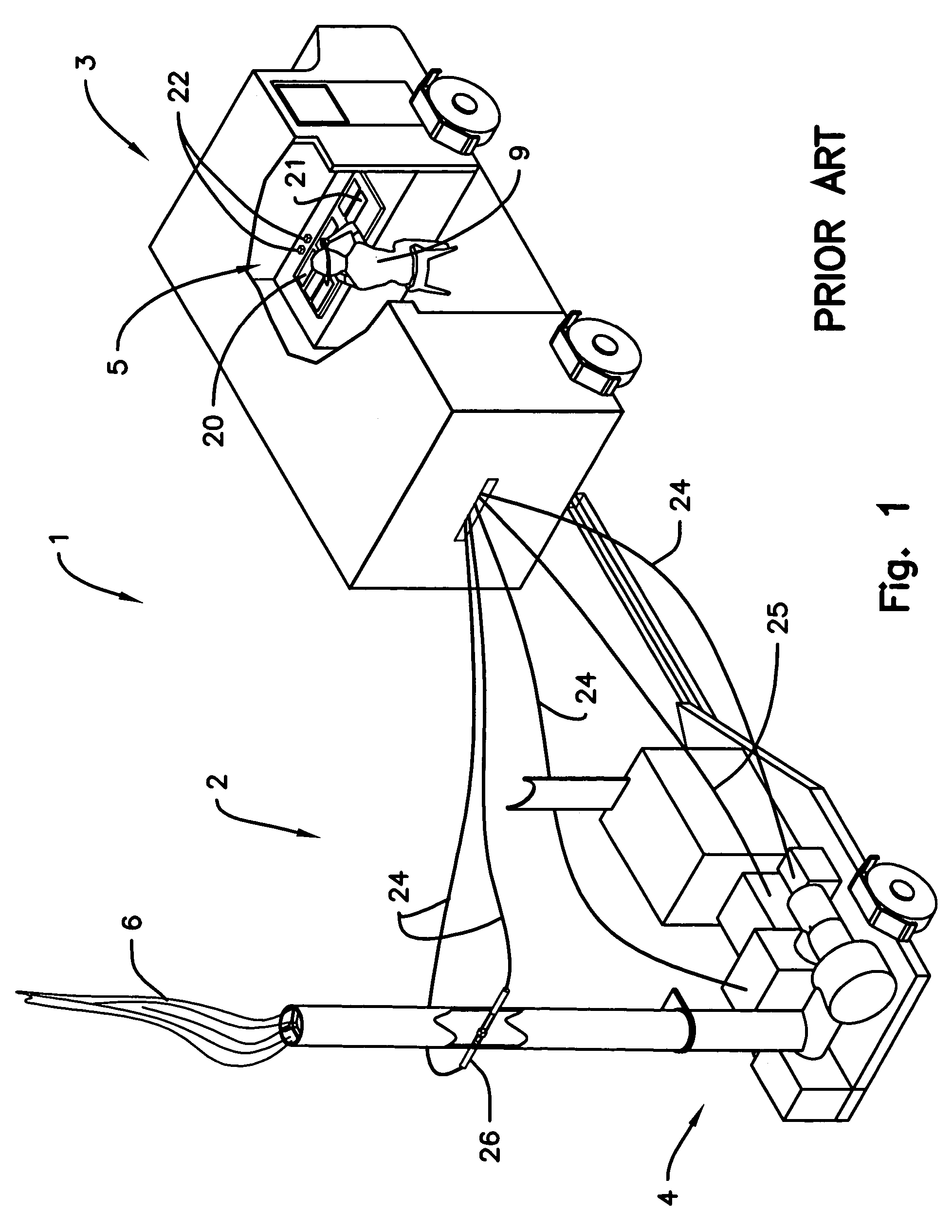
This means of transportation requires that the electronics set-up time, and the calibration of instruments be repeated at each new location taking excessive time and a great deal of effort.
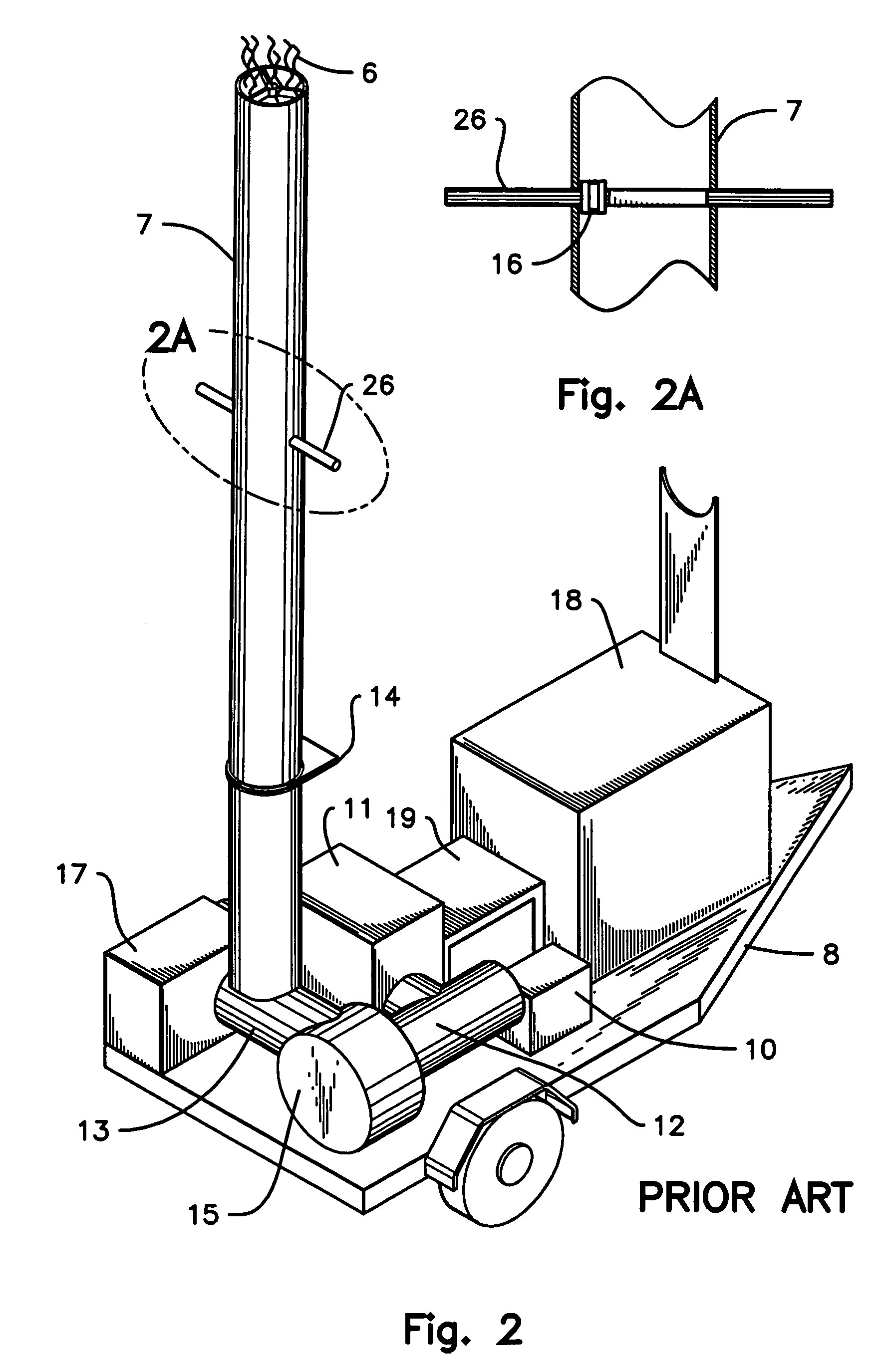
The prior art method used to generate white smoke exiting the smoke stack (7) caused the smoke to pulsate rather than providing a smooth transitional flow of smoke, which created difficulties during calibration of the smoke opacity.
These difficulties arise with the pulsating characteristics of the present centrifugal blower (15), the said pulsating effect causes difficulties in calibrating the smoke opacity.
The prior art centrifugal blower (15) is inefficient in that it requires a high horse power motor, which is costly to operate.
This prior art process is cumbersome and time consuming, including the operating personnel having to work within a soot filled smoke stack (7).
Upon failure of said prior art electric generator (19) the operation of the prior art smoke generator system (1) becomes inoperative thus requiring the cancellation of the training session.

Method used


Image

  • Smoke generator machine
  • Smoke generator machine
  • Smoke generator machine

Examples


Embodiment Construction

)

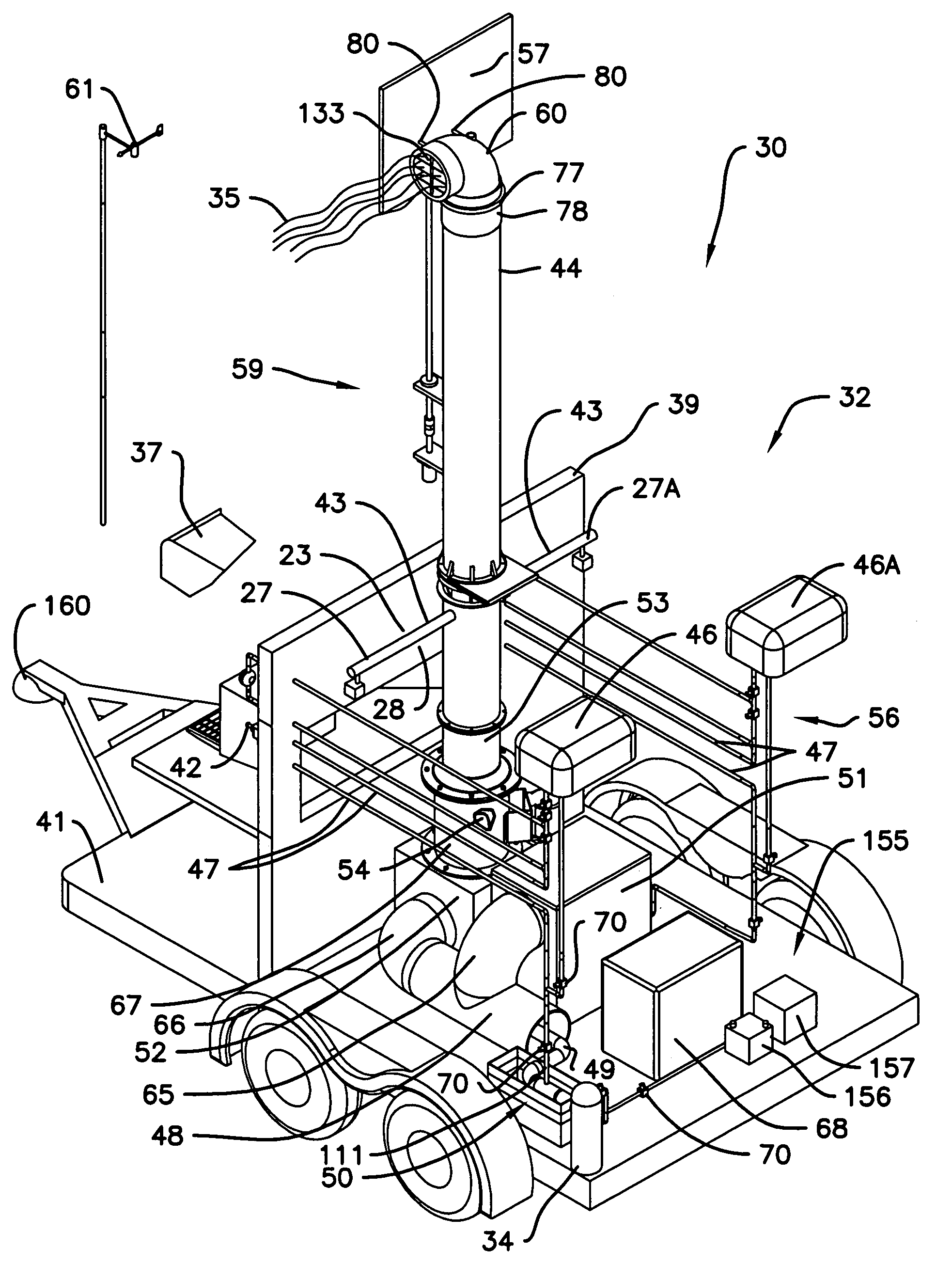
[0068]FIG. 3 is the preferred embodiment illustrating a prospective rear view of the smoke generator (30) with rear doors (31) shown in the open position exposing a portion of the smoke generating components (32), and the side door (33) is shown open to the entrance to the control room (36) separated from the smoke generating component room (32) by a wall (39), with fuel tank (46) and (46A) positioned on top of the trailer cab (37) to provide a gravity-fed head pressure for fuel distribution of the piping system (47), and personnel (38) being tested to visually determine the smoke (35) opacity seated at least fifty yards from the smoke generator (30) during the training session. A wind directional indicator (61) positioned on top of said trailer cab (37) to determine the direction of the prevailing wind.

[0069]FIG. 4 is a front top isometric view of the preferred embodiment with the trailer cover (37) removed to illustrate the control components (5) of the system showing the control...


PUM


Abstract

An improved system and operating method for a smoke generator machine and control room to be enclosed into a single trailer for the training of personnel in the art of visible smoke opacity compliance monitoring of industrial smoke discharge from smoke stacks by distinguishing the variations of smoke opacity emission based on the requirements set forth by the U.S. Environmental Protection Agency EPA said smoke generator is principally used for production of white and black smoke for simulating smoke discharge from industrial smoke stacks by heating various fuels to the flash point in burn boxes to create white or black smoke and venting said smoke through a duct system to a smoke stack by creating a artificial draft by a speed control fan.

Description

FIELD OF INVENTION[0001]The present invention relates, in general, to an improved system, and operating method, for smoke generators used in training of industry and government inspection personnel throughout the United States to be certified, and re-certified yearly in the determination of the opacity emission from smoke stacks. Said personnel are to perform the work based on the United States Environmental Protection Agency (EPA) requirements for compliance monitoring for smoke stack opacity. Our improved invention is related, in particular, to the production of white and black smoke which is used to simulate industrial emission from smoke stacks in use in real time, for the study by, and training of inspection personnel in the visual art of defining smoke opacity.BACKGROUND AND DESCRIPTION OF THE PRIOR ART[0002]Smoke generators have been used to train personnel as observers of visible emissions in the opacity of smoke generated from smoke stacks produced by industrial nations sin...

Claims


Application Information

Patent Timeline
Patent Type & Authority Patents(United States)
IPC IPC(8): F23D14/62
CPCA62C99/0081A01G13/06
Inventor BOSCH, GARRETT EUGENEBOSCH, GARY EUGENE
Owner BOSCH GARRETT
Learn More