Linear guide device

a guide device and linear technology, applied in the direction of linear bearings, shafts and bearings, bearings, etc., can solve the problems of affecting the operation performance of the slider, affecting the operation of the slider, and shortening the life of the retaining piece, so as to suppress the skew of the roller, improve the operating performance, and suppress the increase of the sound level

Active Publication Date: 2009-08-25
NSK LTD
View PDF12 Cites 2 Cited by
  • Summary
  • Abstract
  • Description
  • Claims
  • Application Information

AI Technical Summary

Benefits of technology

[0005]A first object of the present invention is to provide a linear guide device capable of suppressing the skew of a roller to improve the operating performance. Further, a second object of the invention is to provide a linear guide device capable of suppressing increase of a sound level caused by collision between rollers to each other thereby reducing the noise. Further, a third object of the invention is to provide a linear guide device capable of suppressing early wear of a retaining piece and capable of ensuring smooth actuation of a slider. Furthermore, a fourth object of the invention is to provide a linear guide device capable of improving the assembling efficiency.

Problems solved by technology

In the linear guide device described above, in a case where a succeeding roller collides against the preceding roller, it may possibly generate sounds or deteriorate the operating performance of the slider.
However, in a case where the distance between the two adjacent rollers increases during movement of the slider, the retaining piece is in contact with the rail-side raceway surface or the slider-side raceway surface and the retaining piece suffers from early wear to result in a problem of shortening the life of the retaining piece.
In addition, the retaining piece is deformed by the contact of the retaining piece with the rail-side raceway surface, the slider-side raceway surface, etc. to possibly deteriorate the operating performance of the slider.

Method used


Image

  • Linear guide device
  • Linear guide device
  • Linear guide device

Examples


first embodiment

[0055]the present invention is to be described with reference to FIG. 1 to FIG. 8.

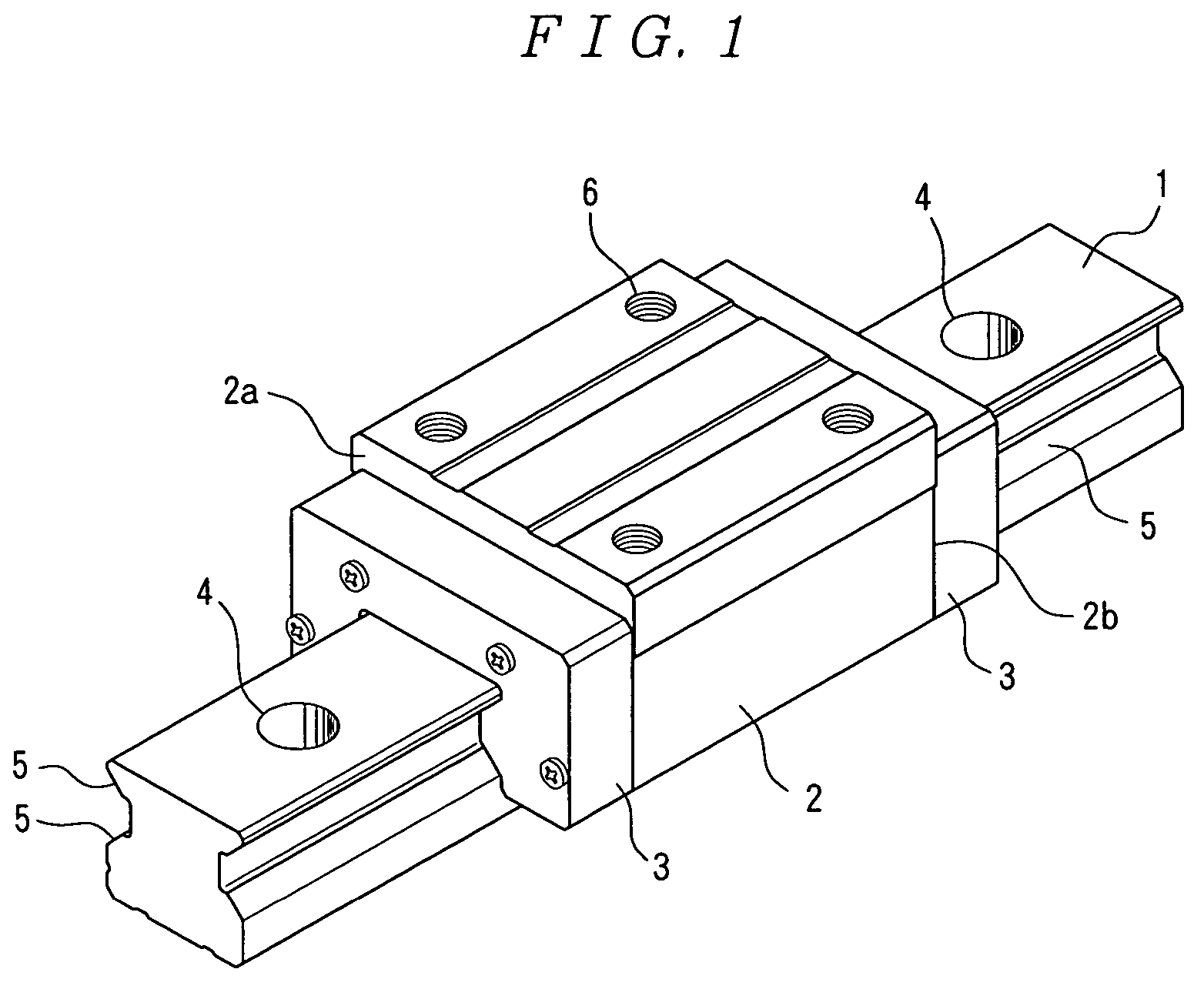
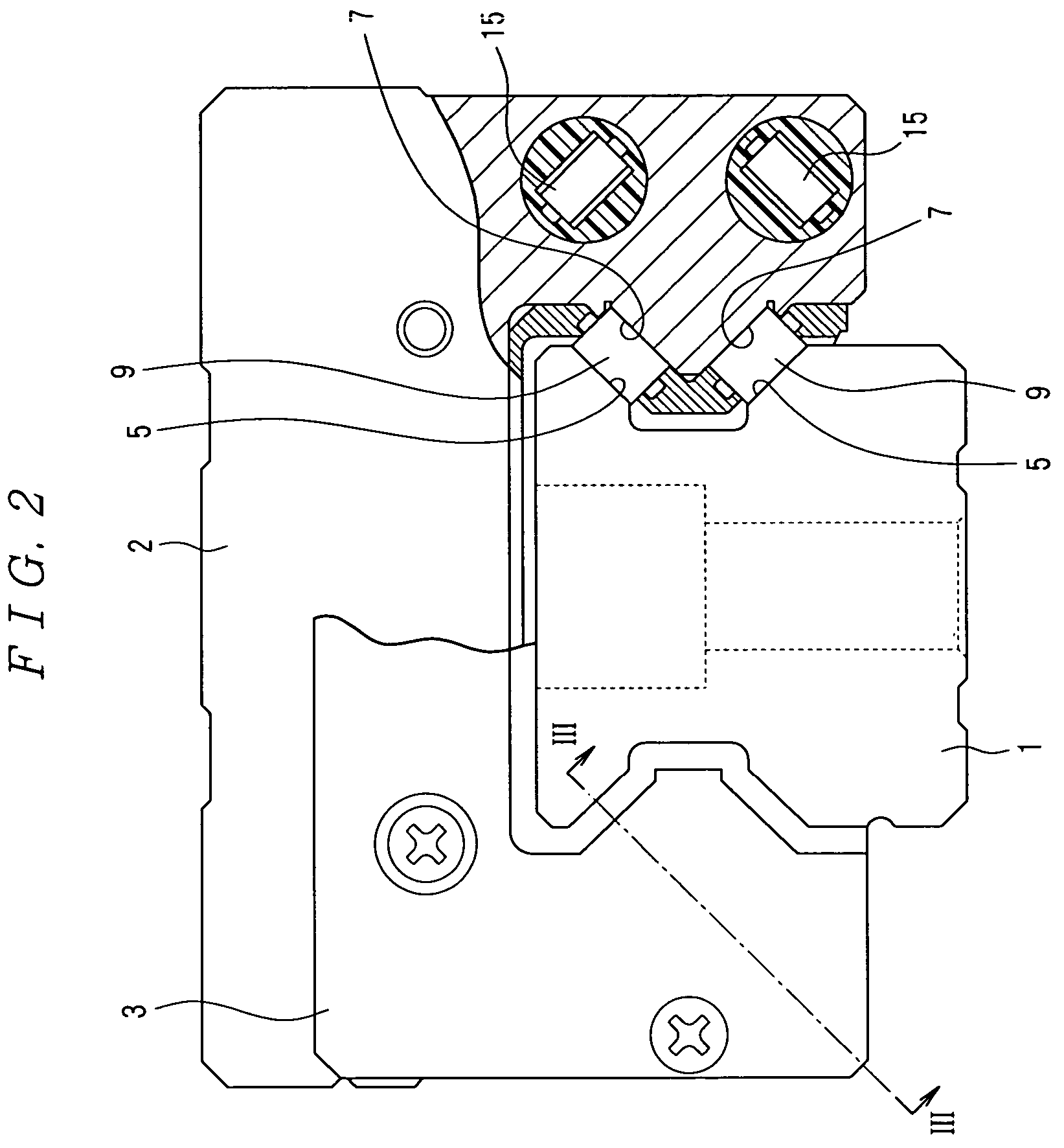
[0056]In FIG. 1, a linear guide device according to the first embodiment of the invention has a rail 1, a slider 2 having a front end face 2a and a rear end face 2b in the longitudinal direction of the rail 1 and two end caps 3 each attached on both end faces 2a and 2b in the front-to-rear direction of the slider 2.

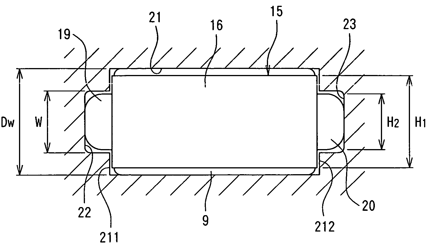
[0057]The rail 1 is formed of a steel material such as an alloy steel. Rail attaching holes 4 for securing the rail 1 on a base of a machine tool by means of not illustrated bolts are perforated in an upper surface of the rail 1 each at a predetermined pitch in the longitudinal direction of the rail 1. Further, the rail 1 is formed into a shape similar to an I-shaped configuration for a cross section along the lateral direction of the rail 1. The rail-side raceway surfaces 5 are formed each by two on a lateral left face and a lateral right face of the rail 1 along the longitudinal direction ...

second embodiment

[0068]Then, the invention is to be described with reference to FIG. 9 to FIG. 20.

[0069]In FIG. 9, a linear guide device according to the second embodiment of the invention has a rail 1, a slider 2 having a front end face 2a and a rear end face 2b in the longitudinal direction of the rail 1 and two end caps 3 each attached on both end faces 2a and 2b in the front-to-rear direction of the slider 2.

[0070]The rail 1 is formed of a steel material such as an alloy steel. Rail attaching holes 4 for securing the rail 1 on a base of a machine tool by means of not illustrated bolts are perforated in an upper surface of the rail 1 each at a predetermined pitch in the longitudinal direction of the rail 1. Further, the rail 1 is formed into a shape similar to an I-shaped configuration for a cross section along the lateral direction of the rail 1. The rail-side raceway surfaces 5 are formed each by two on a lateral left face and a lateral right face of the rail 1 along the longitudinal direction ...

third embodiment

[0089]Then, the invention is to be described with reference to FIG. 21 to FIG. 29.

[0090]In FIG. 21, a linear guide device according to the third embodiment of the invention has a rail 1, a slider 2 having a front end face 2a and a rear end face 2b in the longitudinal direction of the rail 1 and two end caps 3 each attached on both end faces 2a and 2b in the front-to-rear direction of the slider 2.

[0091]The rail 1 is formed of a steel material such as an alloy steel. Rail attaching holes 4 for securing the rail 1 on a base of a machine tool by means of not illustrated bolts are perforated in an upper surface of the rail 1 each at a predetermined pitch in the longitudinal direction of the rail 1. Further, the rail 1 is formed into a shape similar to an I-shaped configuration for a cross section along the lateral direction of the rail 1. The rail-side raceway surfaces 5 are formed each by two on a lateral left face and a lateral right face of the rail 1 along the longitudinal direction...


PUM


Abstract

A linear guide device has a retaining piece (15) between two adjacent rollers (9). The retaining piece (15) has a retaining piece body (16) having left side-face section and a right side-face section that are parallel to the end face sections of the rollers (9), a first arm section (19) extending from the left side-face section of the retaining piece body (16) toward the end face sections of the two adjacent rollers (9) and fitting in a first guide groove (22) formed in one wall surface section of a circulation path (21), and a second arm section (20) provided on the right side-face section of the retaining piece body (16) so as to be parallel to the first arm section (19) and fitting in a second guide groove (23) formed in the other wall surface section of the circulation path (21). The heights of the retaining piece body (16) and the arm sections (19, 20) satisfy the conditional expression of (H1−H2) / 2<(Dw−W) / 2, where H1 is the height of the retaining piece body (16), in the direction perpendicular to the axial direction of a roller; H2 the height of the arm sections (19, 20) in the direction perpendicular to the axial direction of the roller; W the width of the guide grooves (22, 23) in the direction perpendicular to the axial direction of the roller; and Dw the diameter of the roller (9).

Description

TECHNICAL FIELD[0001]The present invention concerns a linear guide device for guiding an object that conducts linear motion in the moving direction thereof and, particularly, it relates to a linear guide device using rollers as rolling elements.BACKGROUND ART[0002]A linear guide device using rollers as rolling elements generally includes a rail having a lateral left face and a lateral right face surface, a slider having a front end face and a rear end face in the longitudinal direction of the rail and end caps each attached on the front end face and the rear end face of the slider, in which slider-side raceway surfaces opposed to rail-side raceway surfaces formed on the lateral left face and the lateral right face of the rail are formed on two opposing inner lateral faces of the slider. Further, the linear guide device of this type has a plurality of rollers. The rollers are adapted to roll through rolling element rolling channels formed between the rail-side raceway surfaces and th...

Claims


Application Information

Patent Timeline
Patent Type & Authority Patents(United States)
IPC IPC(8): F16C29/06F16C19/20F16C19/40F16C33/37F16C33/372F16C33/51
CPCF16C29/06F16C33/3706F16C29/065
Inventor KATO, SOICHIROKURACHI, NOBUHIDEAKIYAMA, MASARUMATSUMOTO, JUN
Owner NSK LTD
Why Eureka
Try Eureka