Wall-mountable timer for an electrical load

a technology of electrical load and timer, which is applied in the direction of electrical appliances, light sources, electric light circuit arrangements, etc., can solve the problems of unsatisfactory aesthetic appearance, high level of cognition, and limited functionality of the user interface of the timer

Active Publication Date: 2009-08-25
LUTRON TECH CO LLC
View PDF52 Cites 36 Cited by
  • Summary
  • Abstract
  • Description
  • Claims
  • Application Information

AI Technical Summary

Benefits of technology

[0010]According to the present invention, a wall-mountable load control device for controlling the power delivered to an electrical load from an AC power source comprises a controllably conductive device, a controller, a toggle actuator, a timer adjustment actuator, and a plurality of visual indicators. The controllably conductive device has a control input and is adapted to be coupled in series electrical connection between the source and the load for controlling the delivery of power to the load. The controller includes a timer and is operatively coupled to the control input of the controllably conductive device to control the conductivity of the controllably conductive device. The toggle actuator, the timer adjustment actuator, and the plurality of visual indicators are operatively coupled to the controller. The controller is operable to select a preset timeout period in response to an actuation of the timer adjustment actuator, cause the visual indicators to display a representation of the preset timeout period, control the conductivity of the controllably conductive device so as to enable the delivery of power to the load in response to a first actuation of the toggle actuator, start the timer, which is initialized with the preset timeout period, in response to the first actuation of the toggle actuator, and control the conductivity of the controllably conductive device so as to prevent the delivery of power to the load when the preset timeout period has elapsed.

Problems solved by technology

However, typical prior art electronic timers have user interfaces that provide limited functionality, require a high level of cognition to operate, and have an unsatisfactory aesthetic appearance.
For example, the Leviton electronic timer does not offer a bypass mode.
Further, the functional buttons and visual indicators of typical prior art electronic timers are not attractive, especially in a residential installation.

Method used


Image

  • Wall-mountable timer for an electrical load
  • Wall-mountable timer for an electrical load
  • Wall-mountable timer for an electrical load

Examples


Embodiment Construction

[0027]The foregoing summary, as well as the following detailed description of the preferred embodiments, is better understood when read in conjunction with the appended drawings. For the purposes of illustrating the invention, there is shown in the drawings an embodiment that is presently preferred, in which like numerals represent similar parts throughout the several views of the drawings, it being understood, however, that the invention is not limited to the specific methods and instrumentalities disclosed.

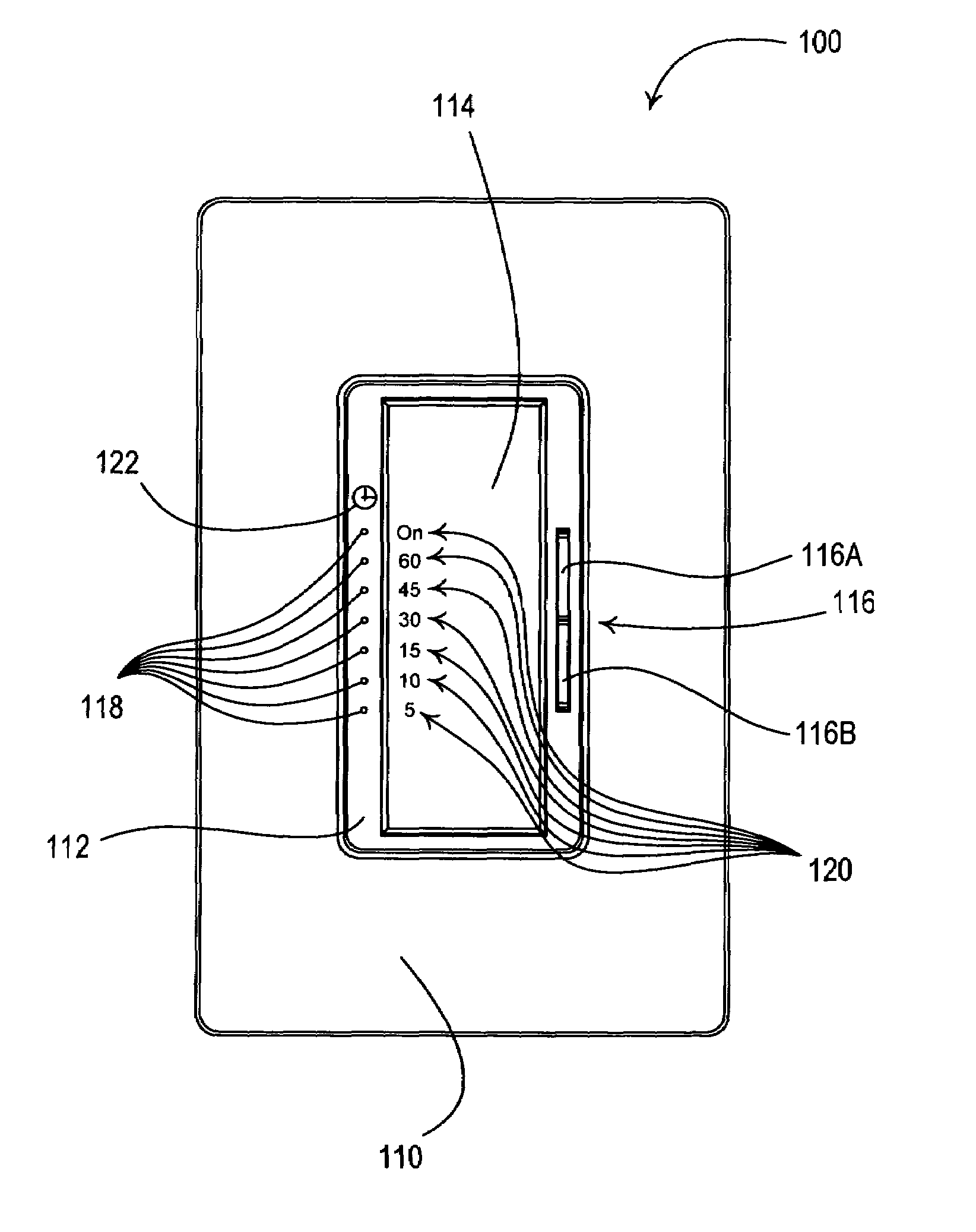
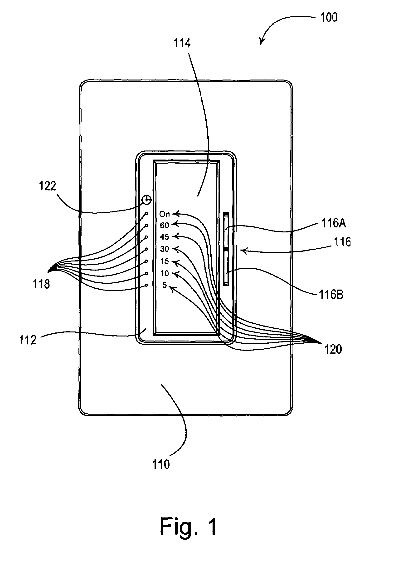
[0028]FIG. 1 is a front view of an electronic timer 100 according to the present invention. The electronic timer 100 comprises a faceplate 110 and a bezel 112 received in an opening of the faceplate. The electronic timer 100 further comprises a toggle actuator 114 and a timer adjustment actuator 116, i.e., a rocker switch. Actuations of the toggle actuator 114 toggle, i.e., turn off and on, a connected electrical load, for example, a lighting load 204 (FIG. 2) or a motor load, s...


PUM


Abstract

A wall-mountable electrical timer for controlling the delivery of power from an AC power source to an electrical load, such as a lamp or a fan motor, includes: a timer adjustment actuator for selecting a predetermined time period of operation for the load; a toggle actuator for starting the timer, turning off the timer, and placing the timer in a bypass mode of operation; a vertical linear array of light-emitting diode visual indicators for indicating the length of a predetermined time period, the time remaining, and whether the timer is in the bypass mode; a controllably conductive device for regulating the delivery of power from the AC source to the load; and a controller for receiving inputs from the timer adjustment actuator and the toggle actuator, and for transmitting outputs to the visual indicators and the controllably conductive device.

Description

BACKGROUND OF THE INVENTION[0001]1. Field of the Invention[0002]The present invention relates to load control devices for controlling the amount of power delivered to an electrical load from a source of alternating-current (AC) power, and more particularly, to a wall-mountable electronic timer for supplying power to a connected electrical load for a predetermined amount of time selectable by a user.[0003]2. Description of the Related Art[0004]In response to increasing awareness of energy conservation, many lighting control devices, such as dimmers, electronic timers, occupancy sensors, and daylight sensors, provide means for energy management of lighting loads in commercial and residential installations. Specifically, electronic timers operate to turn off a connected electrical load after a predetermined amount of time after the electrical load is turned on. Typically, the electronic timer includes a switching device, such as a relay, coupled in series electrical connection between ...

Claims


Application Information

Patent Timeline
Patent Type & Authority Patents(United States)
IPC IPC(8): H01H7/00
CPCH05B37/0281Y02B20/42H05B47/16Y02B20/40
Inventor BLAIR, EDWARD J.DOBBINS, AARONVIGUE, NICOLE R.JACOBY, ELLIOT G.NEWMAN, JR., ROBERT C.
Owner LUTRON TECH CO LLC
Why Eureka
Try Eureka