PWM/PFM control circuit and switching power supply circuit

a control circuit and power supply circuit technology, applied in the direction of power conversion systems, dc-dc conversion, instruments, etc., can solve the problems of ripple voltage increase, output voltage ripple voltage, etc., and achieve the effects of small power consumption, great ripple component, and great power consumption

Active Publication Date: 2009-08-25
TOREX SEMICON LTD
View PDF7 Cites 12 Cited by
  • Summary
  • Abstract
  • Description
  • Claims
  • Application Information

AI Technical Summary

Benefits of technology

[0014]The present invention has been accomplished in the light of the above-mentioned earlier technologies. It is an object of the present invention to provide a PWM / PFM control circuit and a switching power supply circuit, which can decrease a ripple voltage during transition from PFM control under a light load to PWM control under a heavy load to realize a smooth transition of a control mode.
[0029]As a result, if load gradually increases in such a transitional mode, the frequencies of the reference signal and the PWM control signal gradually increase, resulting in a shift to PWM control. In the above transitional mode representing transition from PFM control to PWM control, the present invention enables the output voltage to change gradually.
[0030]Consequently, the ripple voltage in the above-mentioned transitional mode can be dramatically decreased.
[0032]Under PFM control, electric power consumption is small, but the ripple component is great. Under PWM control, by contrast, power consumption is great, but the ripple component can be decreased.

Problems solved by technology

However, in a region where the PFM action is shifted to the PWM action, the PWM control signal S3 enters into a state where certain pulses of the oscillation frequency during the PWM action have been thinned out, posing the problem that the ripple voltage of the output voltage VOUT involves ripples of the oscillation frequency during the PWM action and great pulsations of a low frequency.
However, as paragraph of this publication indicates, the above means encounters the problem that the ripple voltage increases.

Method used


Image

  • PWM/PFM control circuit and switching power supply circuit
  • PWM/PFM control circuit and switching power supply circuit
  • PWM/PFM control circuit and switching power supply circuit

Examples


first embodiment

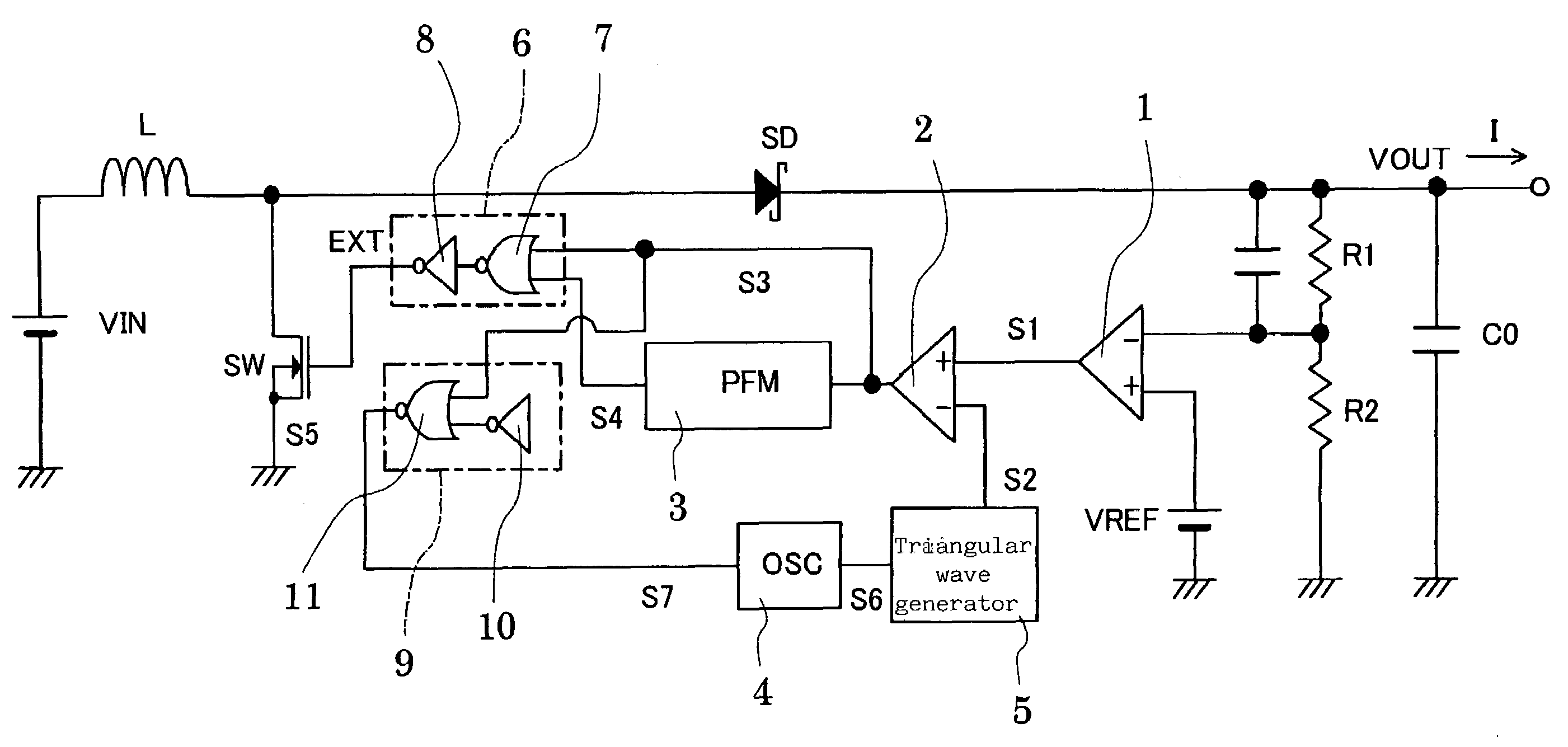
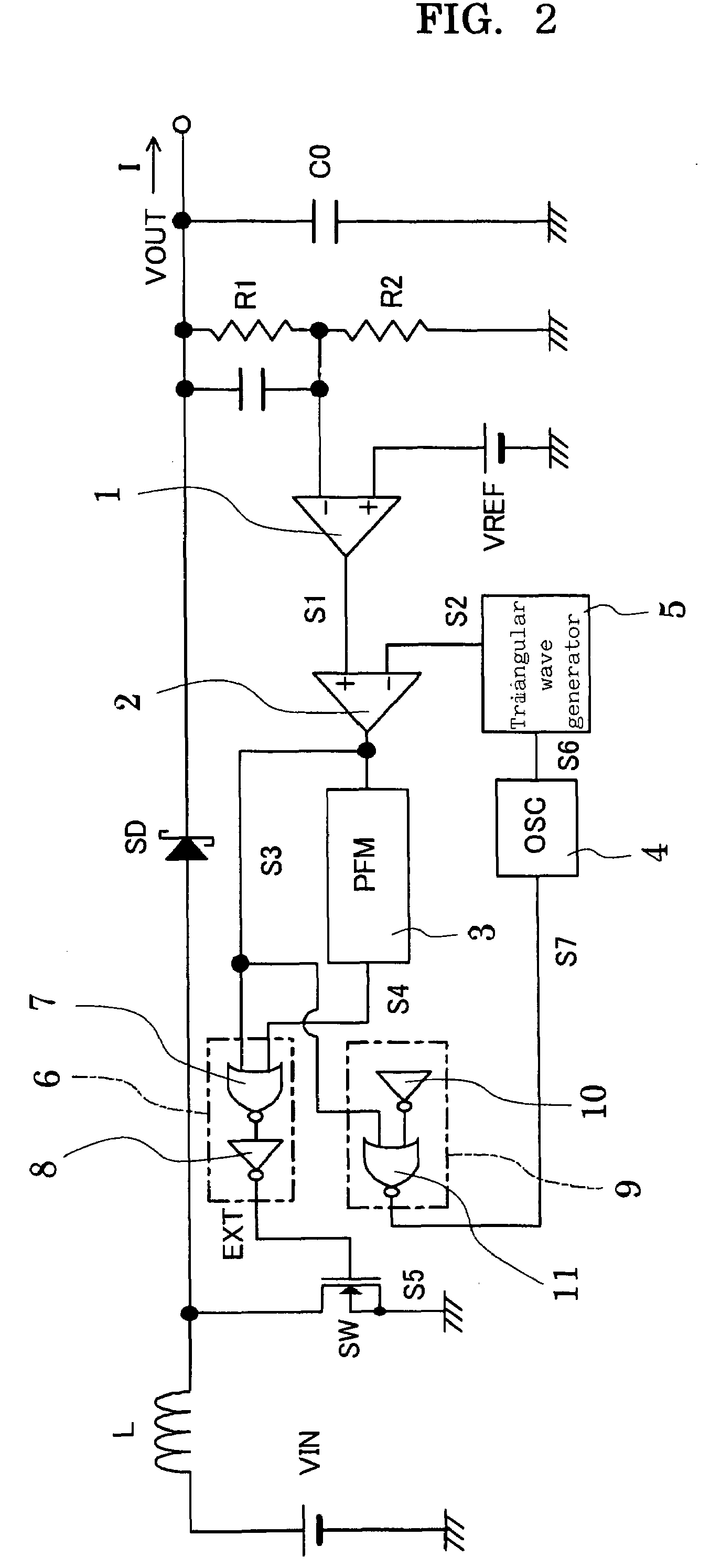
[0047]FIG. 2 is a circuit diagram showing a switching power supply circuit according to a first embodiment of the present invention. This embodiment is a combination of the chopper circuit shown in FIG. 10 and a novel PWM / PFM control circuit. That is, the present embodiment is a switching power supply circuit which has the chopper circuit according to the earlier technology as an object to be controlled.

[0048]However, the object to be controlled need not be limited to such a chopper circuit. No limitations are imposed, as long as the object to be controlled is such that if the load on this object is a heavy load of a predetermined value or higher, the object is operated under PWM control by which the pulse width is determined by this load, and if the load is a light load of less than the predetermined value, the object is operated under PFM control by which the frequency is determined by this load (the same applies in each of the subsequent embodiments).

[0049]As shown in FIG. 2, the...

second embodiment

[0061]FIG. 5 is a circuit diagram showing a PWM / PFM control circuit in a switching power supply circuit according to a second embodiment of the present invention. In the present embodiment, as shown in this drawing, a differential time signal S7 is directly supplied to a triangular wave generator 5, and the oscillation frequency of a ramp signal S2, which is the output signal of the triangular wave generator 5, is controlled based on the differential time signal S7. Other features are exactly the same as those of the PWM / PFM control circuit of the switching power supply circuit shown in FIG. 2. Thus, the same portions as those in FIG. 2 are assigned the same numerals and symbols as in FIG. 2, and duplicate explanations are omitted.

[0062]FIGS. 6A to 6E are timing charts showing the waveforms of respective portions of the PWM / PFM control circuit according to the present embodiment. FIG. 6A represents the relationship between an error signal S1 and the ramp signal S2 as a reference sig...

third embodiment

[0065]FIG. 7 is a circuit diagram showing a PWM / PFM control circuit in a switching power supply circuit according to a third embodiment of the present invention. As shown in this drawing, the PWM / PFM control circuit according to the present embodiment has a PWM comparator 12 and a flip-flop circuit 13. The PWM comparator 12 compares an error signal S1 with a feedback current signal S8 based on a load current I flowing through a chopper circuit which is an object to be controlled, and outputs a reset signal S9 for defining the pulse width of a PWM control signal S3. The flip-flop circuit 13 forms the PWM control signal S3 which rises upon setting by a reference signal S6 as the output signal of an oscillator 4, and which falls upon resetting by the reset signal S9.

[0066]A PFM control signal generator 3 according to the present embodiment forms a PFM control signal S4 based on the reference signal S6.

[0067]In the present embodiment, like the first embodiment, a differential time signa...


PUM


Abstract

A PWM / PFM control circuit has a differential time generating means for forming a differential time signal representing a differential time corresponding to a difference between the pulse width of a PWM control signal and the pulse width of a PFM control signal on condition that the pulse width of the PWM control signal is smaller than the pulse width of the PFM control signal, and the oscillation frequency of a reference signal serving as a reference for forming the PWM control signal is controlled based on the differential time signal to a low value in accordance with the differential time.

Description

[0001]The entire disclosure of Japanese Patent Application No. 2006-272231 filed Oct. 3, 2006 is expressly incorporated by reference herein.BACKGROUND OF THE INVENTION[0002]1. Field of the Invention[0003]This invention relates to a PWM / PFM control circuit and a switching power supply circuit and, more specifically, to those which are useful when improving efficiency under a light load of the switching power supply circuit.[0004]2. Description of the Related Art[0005]Among switching power supply circuits according to earlier technologies is that having a PWM / PFM control circuit which works under PWM control when load is a heavy load of a predetermined value or higher, and works under PFM control when the load is a light load of less than the predetermined value. An example of this type of switching power supply circuit is shown in FIG. 10. As shown in this drawing, such a switching power supply circuit is a combination of a chopper circuit, as an object to be controlled, and a PWM / PF...

Claims


Application Information

Patent Timeline
Patent Type & Authority Patents(United States)
IPC IPC(8): G05F1/40
CPCH02M3/156H02M1/08
Inventor HANE, NORIMASA
Owner TOREX SEMICON LTD
Why Eureka
Try Eureka