Rotor blade system for rotor and rotor case inspection

a technology of rotor blades and rotor cases, applied in the field of inspection systems, can solve the problems of reducing engine efficiency, affecting so as to improve the performance of compressor rotors, accurately determine performance parameters, and minimize the tip clearance

Active Publication Date: 2009-08-25
STANDARD AERO SAN ANTONIO
View PDF12 Cites 13 Cited by
  • Summary
  • Abstract
  • Description
  • Claims
  • Application Information

AI Technical Summary

Benefits of technology

[0007]An object of the invention is to provide a rotor blade system having methods, tools in kit form or otherwise and a use thereof for producing information to correctly align a compressor rotor within a compressor case to achieve the benefits of minimized tip clearance and enhanced performance of a compressor rotor within it's respective compressor rotor case. More specifically, the present invention accurately determines performance parameters to optimally align a compressor rotor within a compressor case. In particular, the invention relates to a rotor blade system for inspecting a blade path on the circumference of a compressor rotor casing and for determining, in sequential order or in a synchronized manner, the position of the compressor rotor in relation to the compressor rotor case using wireless, wired or both, a laser probe, capacitance probe or both to scan about a compressor rotor blade path of the compressor rotor case with a rotor positioner having an encoder, transmitter, receiver or combinations thereof. The system uses information gathered about the position of the compressor rotor in relation to information gathered about the compressor rotor case to produce accurate and efficient operational performance parameters.
[0012]In a further preferred embodiment the probe holder is made of a non-scratchable material for preventing damage to a surface of the rotor blade, that material being natural, manmade or both.
[0019]In a further preferred embodiment, the present invention provides a second fixture for releasable attachment to the compressor rotor, compressor rotor case or both for operably moving said probe about said rotor blade path. The second fixture having a body, a handle attached therefrom, an elongate member extending centrally from a proximal end of the body to a distal end for complementary engagement with a portion of the compressor rotor, the second fixture also having an encoder, transmitter, receiver or a combination thereof that are releasably attached thereon or therein or both.
[0020]A further embodiment of the present invention provides a first implement of the kit for releasably engaging the probe holder, the first implement having a hinged body with an operably actuated proximal handle for effecting a toothed jaw of a distal portion of the body. A second implement of the kit of the present invention preferably provides for setting a pre-determined distance for establishing a zero-point between the probe and the rotor case, said second implement having an elongate, tapered body for ease of insertion and measurement.
[0021]In a preferred embodiment, the present invention provides the probe holder of the inspection kit with a body dimensioned for receiving and transmitting information from said probe holder, probe or both, the body is further dimensioned for receiving the rotor blade of the compressor rotor. In an even further embodiment of the present invention part of the body is made of a non-scratchable manmade or natural material for preventing damage to a surface of the rotor blade, in particular the material would be nylon.

Problems solved by technology

Incorrect positioning of the compressor rotor within its respective compressor case will result in dubious performance parameters leading to blade clearance variations.
These variations can be due to a number of factors including loads on both static and rotating parts and the wear of these parts.
In certain situations excessive blade clearance between the rotor blades and surrounding case can result in reduced engine efficiency.
Accordingly, the performance of the gas turbine engine can be adversely affected by having a non-optimal placement of the compressor rotor within its respective compressor case.
More specifically, off-centre positioning of the compressor rotor will increase the clearance in one area around a circumference of the compressor case but at the same time inadvertently increase the risk of a tip rub situation in opposite areas of the compressor case circumference.
However, in an attempt to optimize compressor rotor performance and subsequently reduce blade tip clearance problems, the accuracy of those systems and methods appear to be compromised by the very nature of the systems and methods used resulting in the aforementioned problems including but not limited to engine lock-up.

Method used


Image

  • Rotor blade system for rotor and rotor case inspection
  • Rotor blade system for rotor and rotor case inspection
  • Rotor blade system for rotor and rotor case inspection

Examples


Embodiment Construction

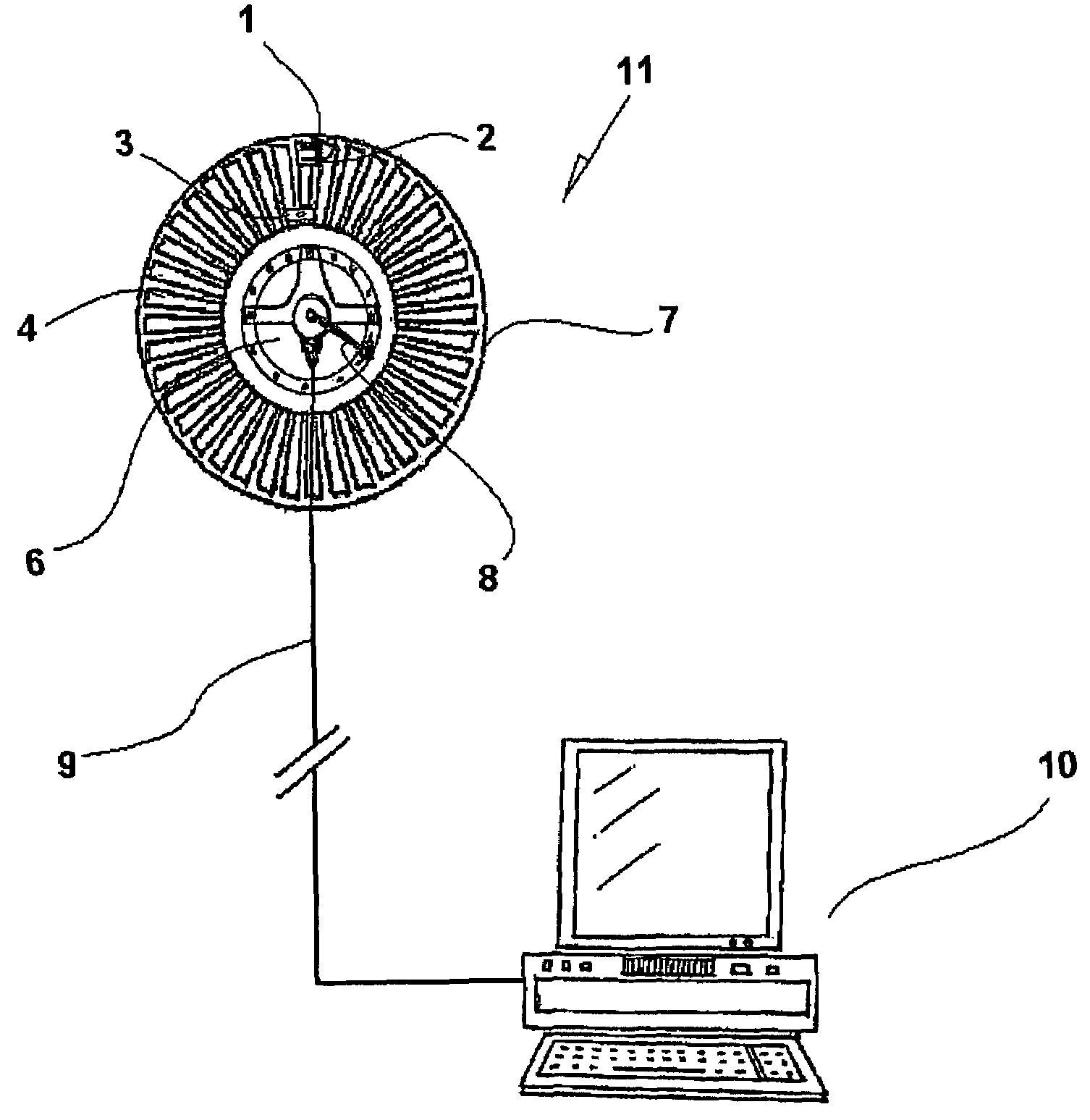
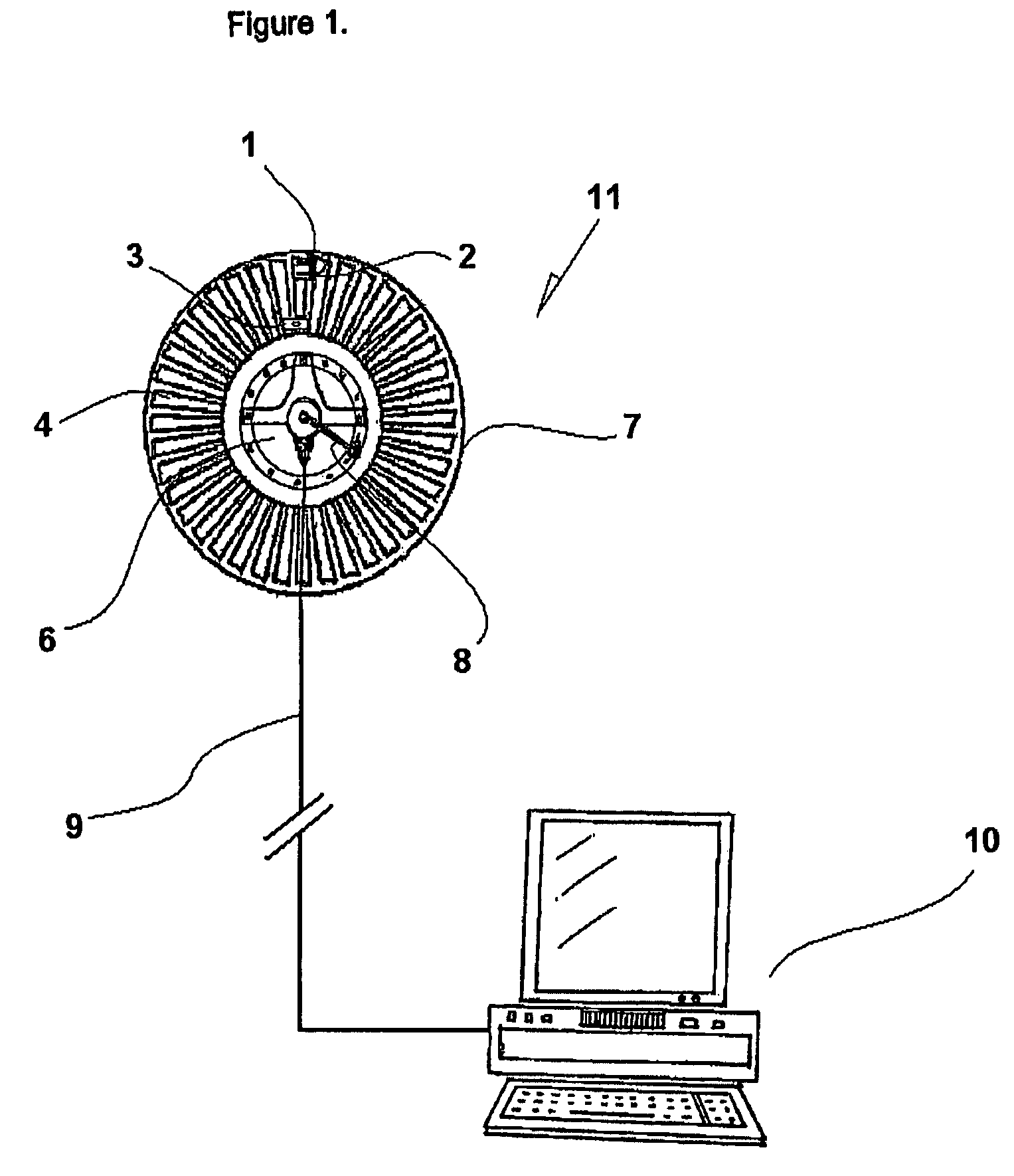
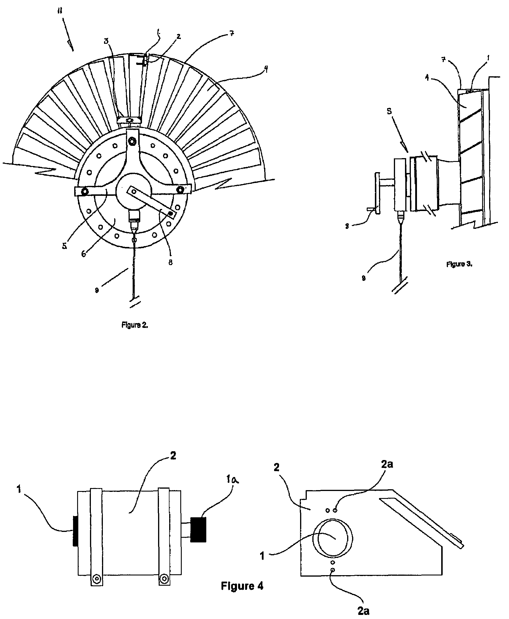
[0031]Although other applications may be envisioned for inspection systems of compressor rotor cases and the rotor blade path thereof, the application of the present invention is particularly advantageous for accurately determining the position of a compressor rotor within its respective compressor case. Accordingly, without intending to limit the present invention to the embodiments described herein, the invention will be described below in further detail having regard to the system, a method and apparatus applied in the system and in particular the use of specialized equipment for the probe inspection system including features used therein as shown in FIGS. 1 to 7.

[0032]FIG. 1, shows an embodiment of the present invention providing a rotor blade system. A probe holder 2 has a probe 1, the probe holder 2 is attached to a rotor blade 4 of a compressor rotor 6 using means to secure the probe holder 2 to prevent movement of the probe 1 about the rotor blade 4 when in scanning motion a...


PUM


Abstract

The present invention relates to a system used for inspecting the position of a compressor rotor within a compressor rotor case. A compressor rotor blade is moved about the rotor blade path of the compressor rotor case, a probe holder attached to the rotor blade has a scanning device as part of the holder used for gathering information relative to the compressor rotor case. A fixture attached to the compressor rotor gathers information about the position of the compressor rotor with respect to the compressor rotor case to determine the relative position of both the compressor rotor in relation to the compressor rotor case.

Description

FIELD OF INVENTION[0001]The present invention relates to an inspection system. More specifically, the invention relates to a rotor blade system for inspecting the position of a compressor rotor in relation to its compressor rotor case.BACKGROUND OF THE INVENTION[0002]The inspection of a compressor casing is generally conducted by measuring a gap between the tip of rotor blades and the compressor case blade path.[0003]The rotor blades and the blade path of the compressor case are an area of critical concern both in the assembly and the operation of turbine engine technology, in particular gas turbine engine technology used in the aerospace industry. Incorrect positioning of the compressor rotor within its respective compressor case will result in dubious performance parameters leading to blade clearance variations. Accordingly, blade clearance can vary over the operating points of a gas turbine engine including during ground idle, takeoff, cruise or deceleration as well as over the c...

Claims


Application Information

Patent Timeline
Patent Type & Authority Patents(United States)
IPC IPC(8): G01R23/20F01D5/00
CPCG01B7/14G01B11/2518G01B11/14G01B7/285
Inventor DUCHEMINSKY, KEVIN M.BEACH, KEVIN C.
Owner STANDARD AERO SAN ANTONIO
Why Eureka
Try Eureka