Window-wiping device, particularly for a motor vehicle

a technology for windshield wipers and motor vehicles, which is applied in the direction of vehicle cleaning, furniture joining parts, domestic applications, etc., can solve the problems of inability to repair, high manufacturing cost, and less pedestrian injury, and achieve the effect of increasing the service life of the windshield wiper devi

Inactive Publication Date: 2009-09-01
ROBERT BOSCH GMBH
View PDF13 Cites 9 Cited by
  • Summary
  • Abstract
  • Description
  • Claims
  • Application Information

AI Technical Summary

Benefits of technology

[0003]The windshield wiper device has the advantage that an attachable embodiment of the element produces the possibility of pedestrian impact protection for windshield wiper devices that is very cost-effective, efficient and simple to dimension. In addition, the attachability results in a particularly simple manufacture and repair of the windshield wiper device, making further cost savings possible in terms of assembly.
[0004]It is especially advantageous if the element is arranged in such a way that it is deformable, in particular compressible, with the effect of a force in the axial direction on the first end of the wiper shaft. In this way, the energy during an impact is absorbed especially well.
[0005]In a particularly simple and cost-effective design the element is arranged between the bearing housing and a projection on the wiper shaft.

Problems solved by technology

If a pedestrian now impacts the wiper arm or the wiper shaft in the case of an accident, these are able to recede, which can result in a lesser injury to the pedestrian.
However, these types of elements are expensive and cost-intensive to manufacture and cannot be repaired after an impact.

Method used


Image

  • Window-wiping device, particularly for a motor vehicle
  • Window-wiping device, particularly for a motor vehicle
  • Window-wiping device, particularly for a motor vehicle

Examples


Embodiment Construction

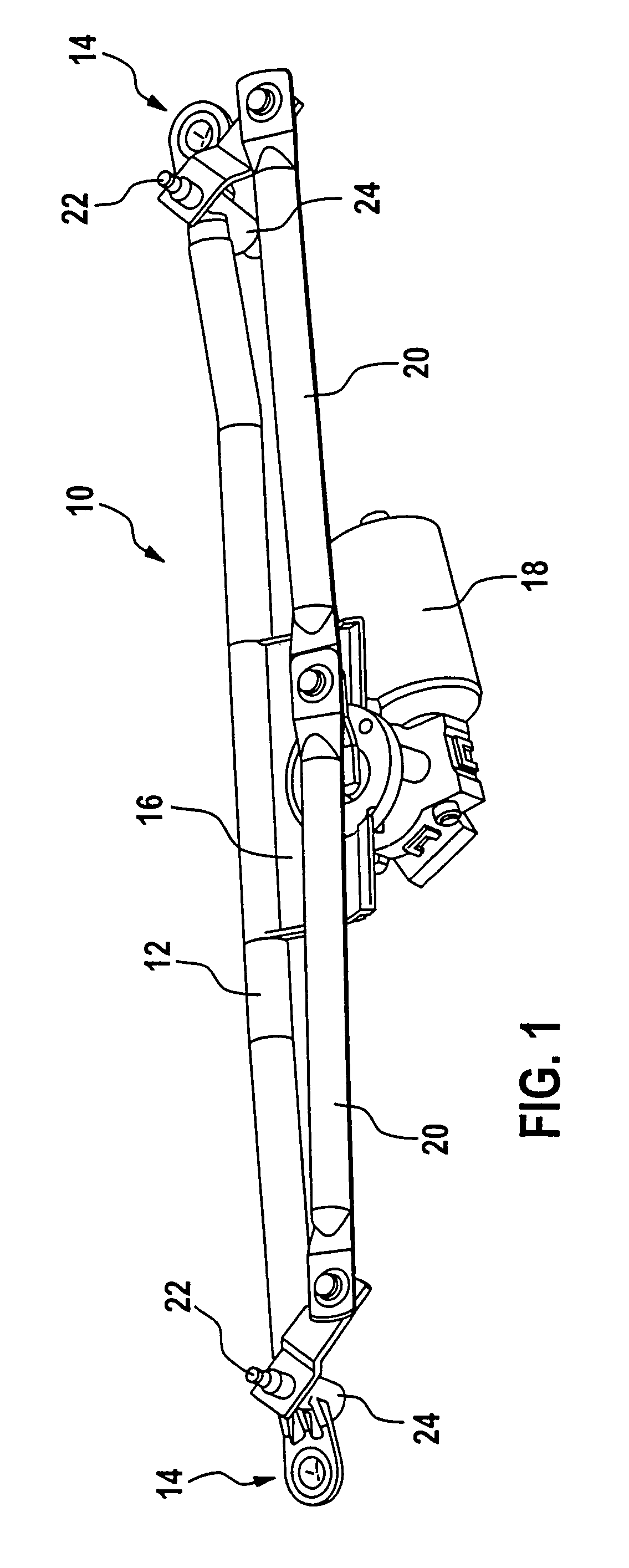
[0020]FIG. 1 shows a perspective representation of a windshield wiper device 10 in accordance with the invention. This is comprised essentially of a support tube 12, which bears a wiper bearing 14 on each of the ends of its longitudinal extension. In addition, a motor support 16 that bears a wiper motor 18 is fastened on the support tube 12. This wiper motor 18 drives wiper shafts 22, which are positioned in the bearing housings 24 of the wiper bearing 14, via thrust rods 20.

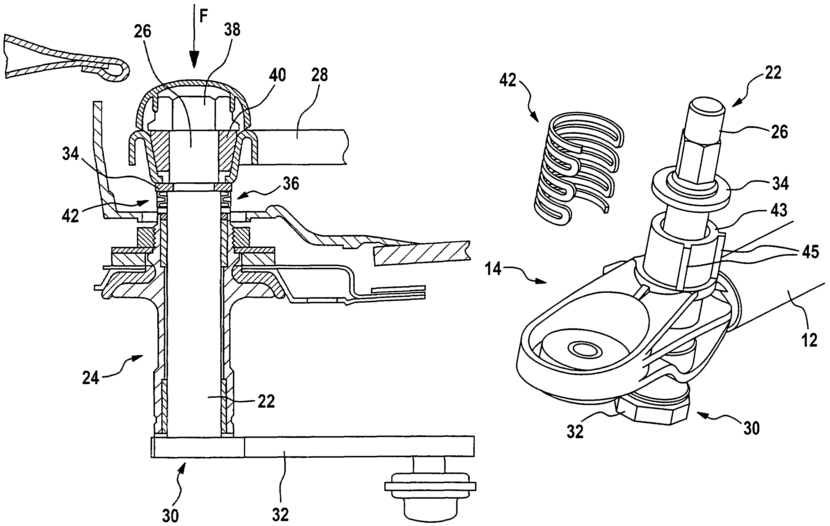
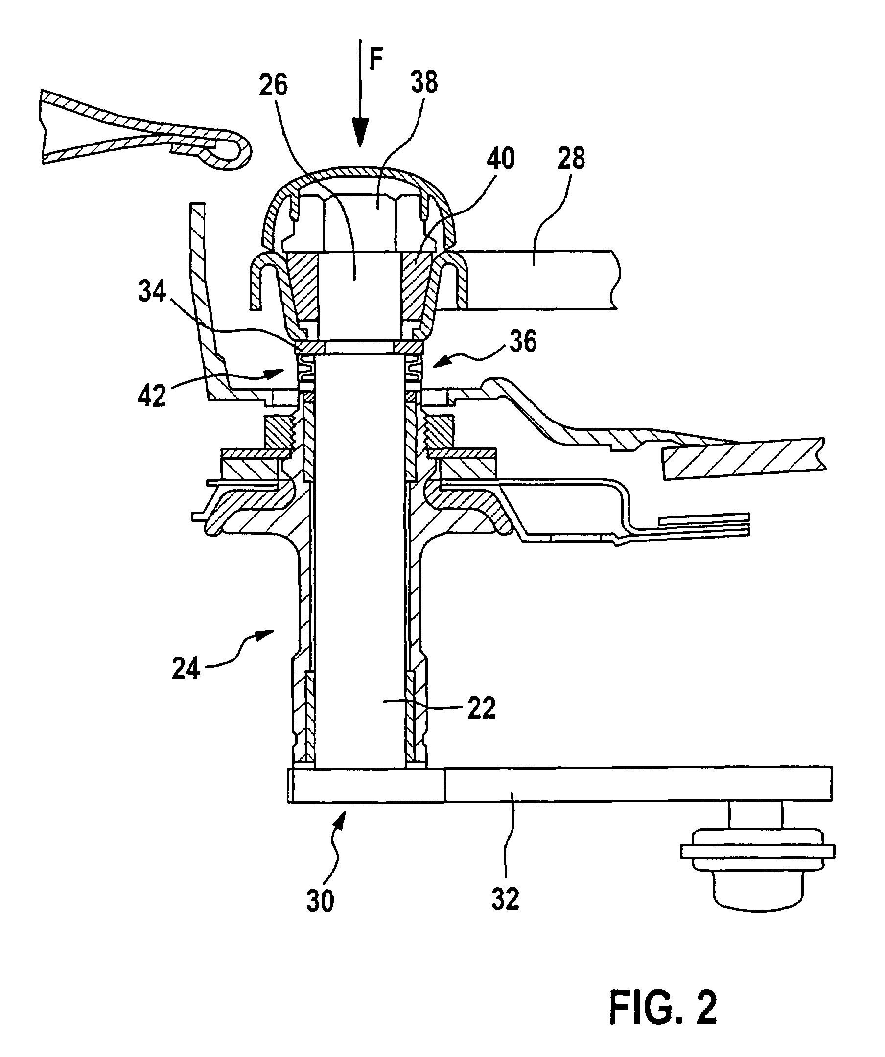
[0021]FIG. 2 depicts in detail a schematic cross-section of a wiper bearing of a windshield wiper device 10 in accordance with the invention.

[0022]The wiper shaft 22 is positioned in the bearing housing 24 of the wiper bearing 14. It has a first end 26, at which it is connected in a torque-proof manner with a wiper arm 28 that is shown only partially here. On the other end 30 of its longitudinal extension, the wiper shaft 22 is connected in a torque-proof manner with a drive crank 32, which is in turn connected ...


PUM


Abstract

A windshield wiper device (10), in particular for a motor vehicle, is proposed, with at least one wiper bearing (14), which includes a bearing housing (24), [and] a wiper shaft (22), which is positioned in the bearing housing (24) and bears a wiper arm (28) on a first end (26). An element (42), which axially fixes the wiper shaft (22), is radially attachable to the wiper shaft (22).

Description

BACKGROUND[0001]The invention relates to a windshield wiper device for a motor vehicle.[0002]Numerous windshield wiper devices, which feature a wiper bearing that includes at least one bearing housing in which a wiper shaft is positioned, which is axially fixed by means of an element and bears a wiper arm on a first end, are already known, e.g., from DE 199 03 140 A1. In this connection, the axial fixation is embodied in such a way that the element is deformed with the effect of force on the wiper arm or on the first end of the wiper shaft under the absorption of energy. If a pedestrian now impacts the wiper arm or the wiper shaft in the case of an accident, these are able to recede, which can result in a lesser injury to the pedestrian. The fact that the element absorbs energy also prevents the pedestrian from impacting the vehicle body with the full energy because of the receding of the wiper arms. For this reason, the elements are embodied as thin-walled, plate-shaped sheet metal...

Claims


Application Information

Patent Timeline
Patent Type & Authority Patents(United States)
IPC IPC(8): B60S1/16B60S1/18B60S1/34B60S1/04
CPCB60S1/0488Y10S403/03B60S1/04
Inventor ZIMMER, JOACHIM
Owner ROBERT BOSCH GMBH
Why Eureka
Try Eureka