
Front suspension arms

a front suspension arm and arm technology, applied in the direction of snowmobiles, rider propulsion, transportation and packaging, etc., can solve the problems of shocks and vehicle damage to the front suspension arm, and achieve the effect of greater strength

Active Publication Date: 2009-09-01
YAMAHA MOTOR CO LTD
View PDF14 Cites 6 Cited by
  • Summary
  • Abstract
  • Description
  • Claims
  • Application Information

AI Technical Summary

Benefits of technology

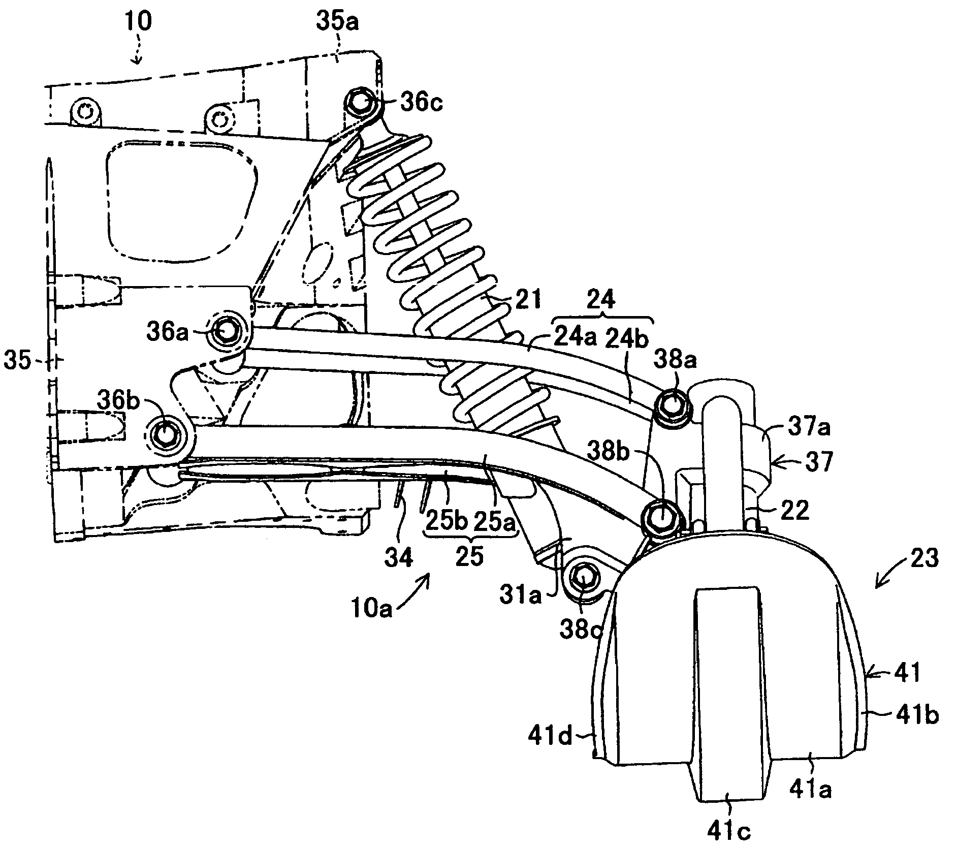
The present invention provides a front suspension arm that is less likely to collide with obstacles and has greater strength against impact forces from the front. The front suspension arm has a bent shape with a first end located vertically higher than the second end, and includes a support member with an aperture extending at least part way through the support member. The front suspension arm also includes first and second arms with connecting members attached to the support member. The first and second arms have a generally linear portion and a bent portion, and at least a portion of the arms has a cross-section in which a vertical dimension is smaller than a dimension generally perpendicular to the vertical dimension. This design improves the vehicle's stability and control while driving on uneven surfaces.

Problems solved by technology

When the front suspension arm collides with such obstacles, the vehicle may experience shocks or the vehicle may incur damage to the front suspension arm.

Method used


Image

  • Front suspension arms
  • Front suspension arms
  • Front suspension arms

Examples


Embodiment Construction

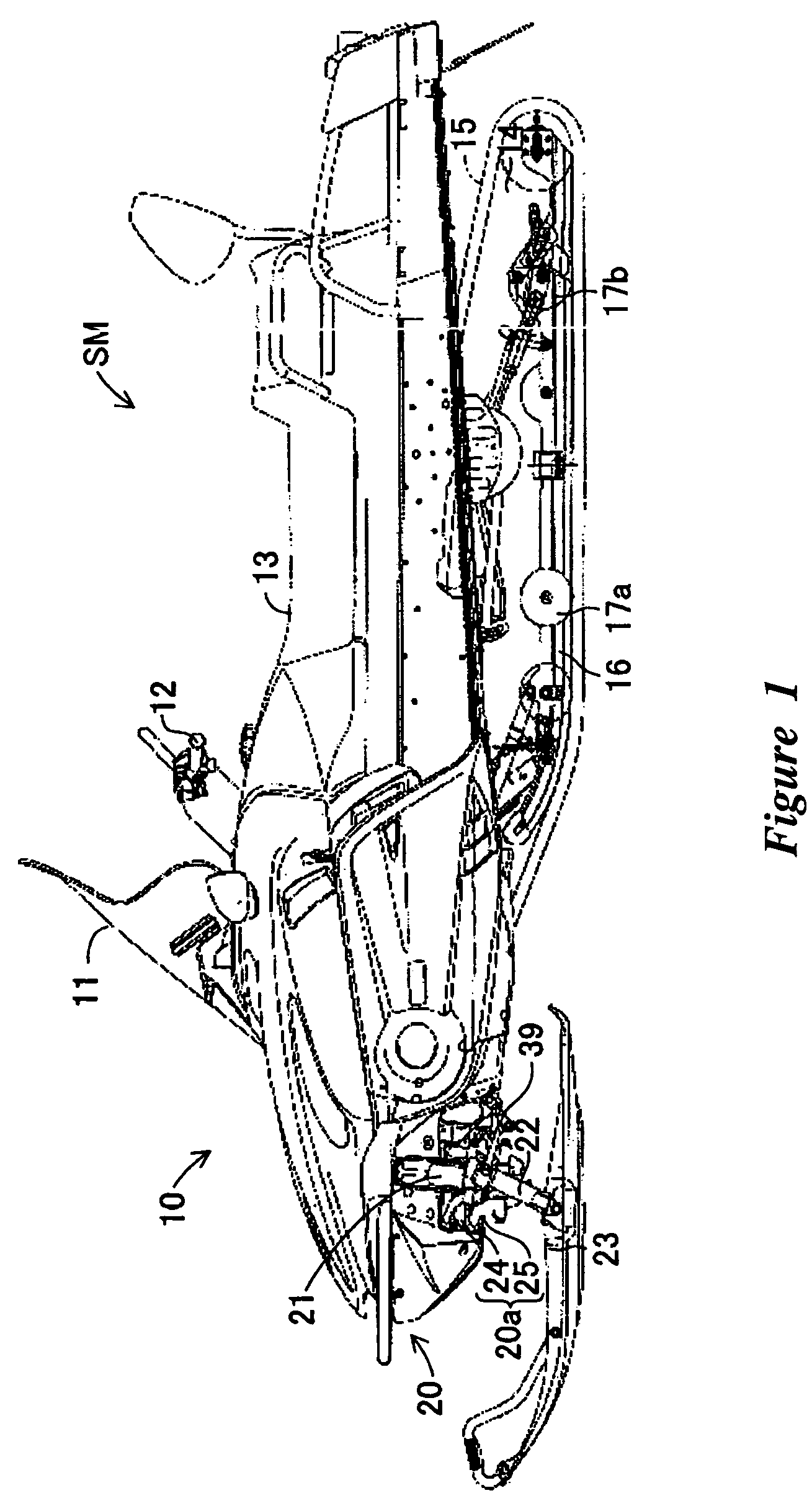
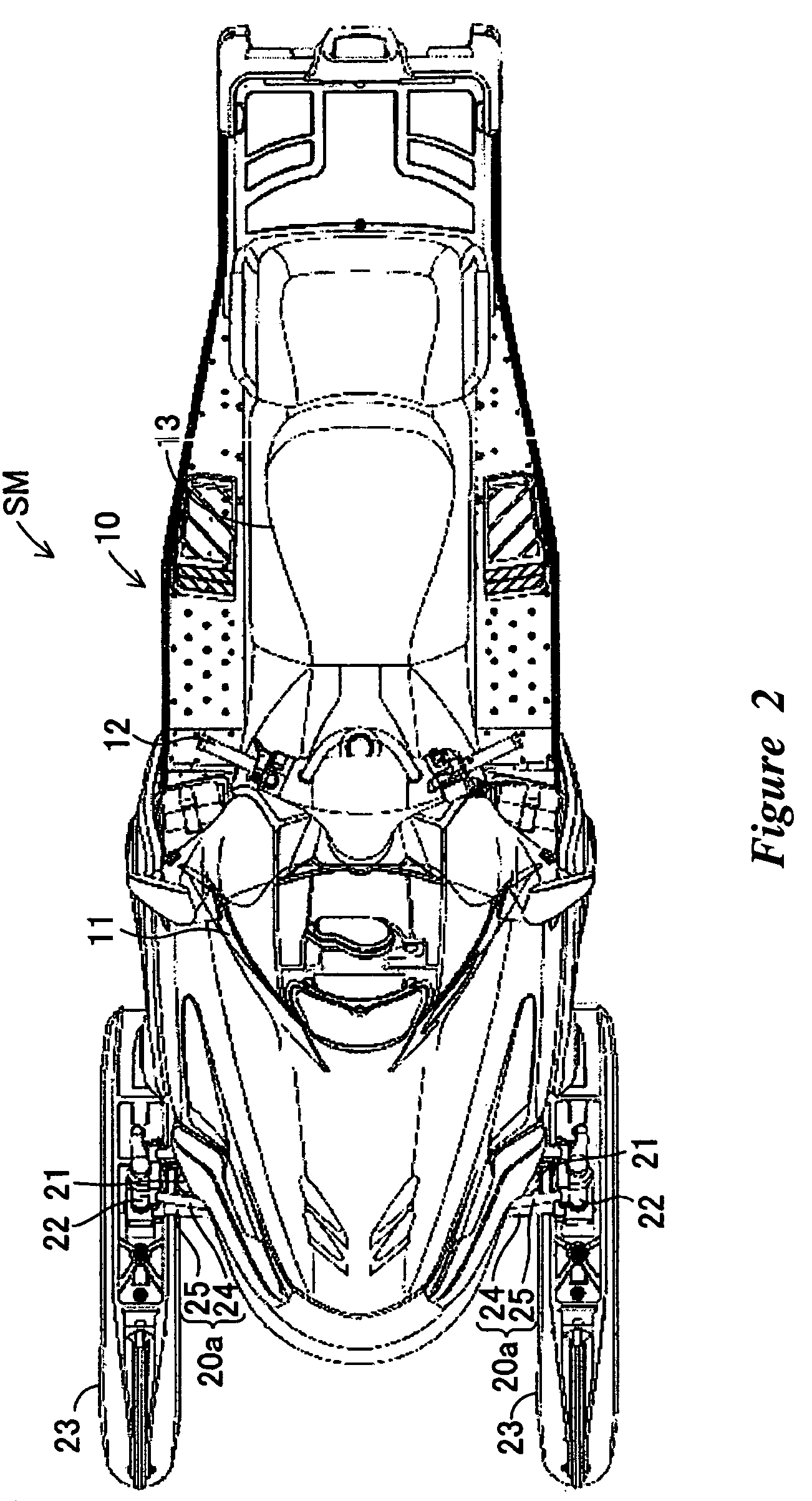
[0026]With reference initially to FIGS. 1 and 2, a snowmobile SM comprises front suspension arms 20a that are arranged and configured in accordance with certain features, aspects and advantages of the present invention. While the front suspension arms 20a will be described with reference to the snowmobile SM, certain features, aspects and advantages of the present invention also can be used with other types of vehicles. For instance, certain features, aspects and advantages of the present invention can be used with all terrain vehicles, dune buggies, small utility vehicles and the like.

[0027]With continued reference to FIGS. 1 and 2, a wind shield 11 can be mounted on a forward portion of the snowmobile SM. Preferably, the wind shield 11 can be positioned along an upper portion of a body 10 of the snowmobile SM. The body 10 comprises a main portion of the snowmobile SM.

[0028]A handle bar 12 or other directional control component can be positioned rearward of the wind shield 11. The ...


PUM


Abstract

A front suspension arm is formed such that it is less likely to collide with obstacles exposed above the surface over which the associated vehicle is operated. The arm also has a greater strength against impact forces from the front. In one configuration, the front suspension arm has a relatively straight portion that is positioned on a body side and the front suspension arm has a bent portion that is formed on the ground contacting element side. The front suspension arm can have two arms having an oblong or oval shape in cross section.

Description

CROSS-REFERENCE TO RELATED APPLICATIONS[0001]The present application claims the priority benefit of Japanese Patent Application No. 2005-027464, filed on Feb. 3, 2005, which is incorporated by reference in its entirety.BACKGROUND OF THE INVENTION[0002]1. Field of the Invention[0003]The present invention generally relates to a vehicle suspension component. More particularly, the present invention relates to a front suspension arm that is provided between a forward portion of a vehicle body and a steering member that is positioned lower than, and to one side of, the forward portion of the vehicle body.[0004]2. Description of the Related Art[0005]Snowmobiles are used to travel over snow-covered terrain. To provide forward drive, a track belt extends over the drive wheels and the rear wheels that are positioned below the vehicle body. An engine drives the track belt to drive the snowmobile.[0006]The snowmobile also comprises steering handle bars that can be positioned in a central trans...

Claims


Application Information

Patent Timeline
Patent Type & Authority Patents(United States)
IPC IPC(8): B62M29/00
CPCB60G3/20B62M27/02B60G2200/144B60G2206/012B62M2027/026B60G2206/8103B60G2300/322B60G2206/121
Inventor KUBOTA, TAKAHIKO
Owner YAMAHA MOTOR CO LTD
Learn More