Bicycle rear wheel suspension system with controlled variable shock rate

a rear wheel suspension and control variable technology, applied in the field of rear wheel suspension apparatus with controlled variable shock rate, to achieve the effect of improving bicycle control characteristics, increasing traction and control, and increasing rider comfor

Active Publication Date: 2009-09-01
SANTA CRUZ BICYCLES
View PDF25 Cites 116 Cited by
  • Summary
  • Abstract
  • Description
  • Claims
  • Application Information

AI Technical Summary

Benefits of technology

[0009]It is an advantage of the bicycle of the present invention that it increases traction and control by keeping the rear wheel on the ground.
[0010]It is another advantage of the bicycle of the present invention that it increases rider comfort by providing more vertical wheel travel for a given bump.
[0011]It is a further advantage of the bicycle of the present invention that it includes a rear wheel suspension system having a rate of change of the shock rate with respect to the vertical wheel travel that has a change in sign, which provides for better bicycle control characteristics.
[0012]It is yet another advantage of the bicycle of the present invention that it has a rear suspension system having a rate of change of the shock rate with respect to the vertical wheel travel that has a change in sign from negative to positive which provides better control for preventing the end of the vertical wheel travel from bottoming out.
[0013]It is yet a further advantage of the bicycle of the present invention that it has a rear suspension system having a rate of change of the shock rate with respect to the vertical wheel travel that has a change in sign from positive to negative which provides for maximizing vertical wheel travel when used with a shock absorber that has an increasing spring rate.

Problems solved by technology

Many of these suspension systems are complicated structures involving a plurality of frame members, linkages of the swingarm frame members to other bicycle frame members and the installation of a shock absorber within the frame members to control the motion of the swingarm and the rear wheel engaged therewith.

Method used


Image

  • Bicycle rear wheel suspension system with controlled variable shock rate
  • Bicycle rear wheel suspension system with controlled variable shock rate
  • Bicycle rear wheel suspension system with controlled variable shock rate

Examples


first embodiment

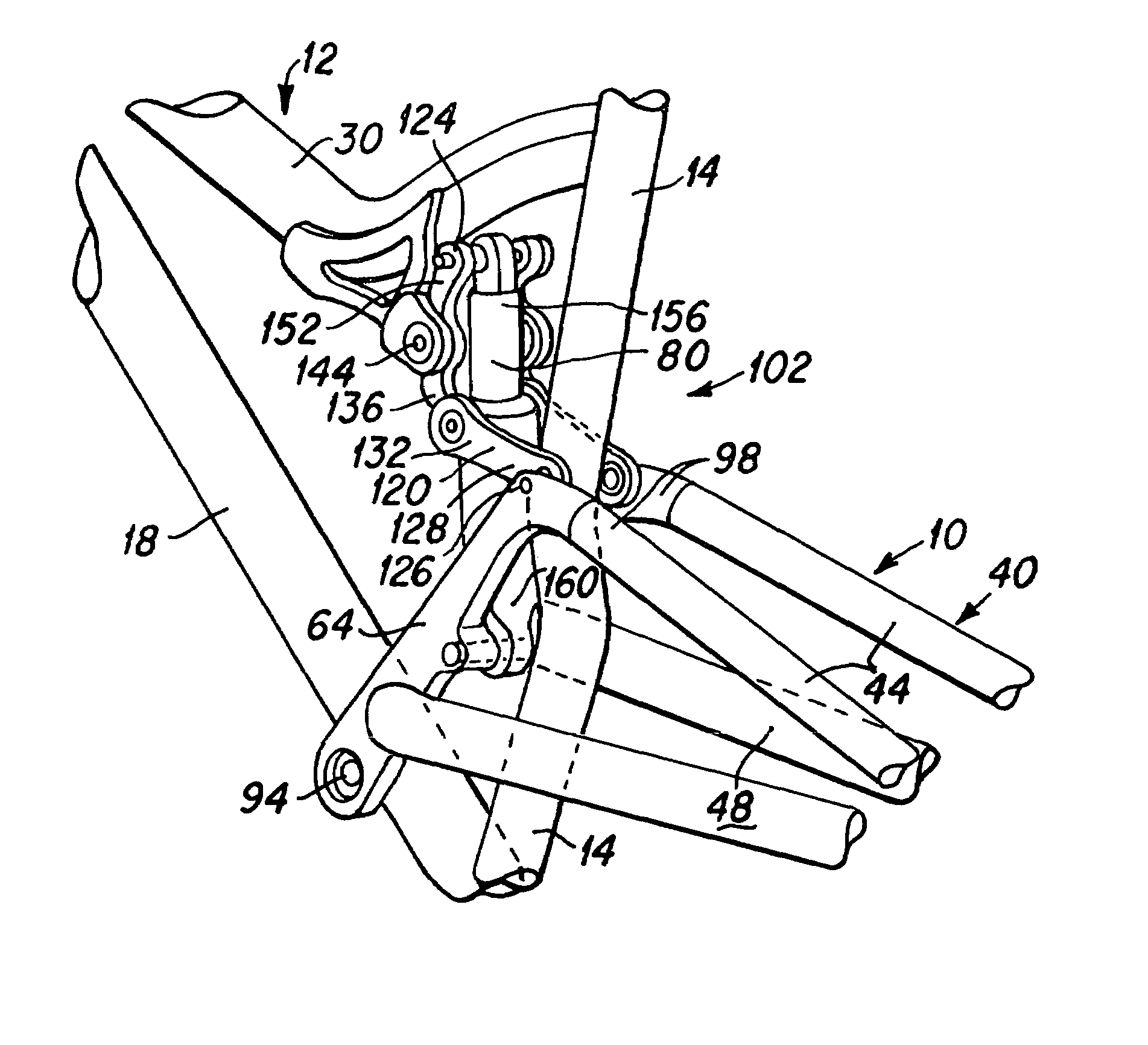
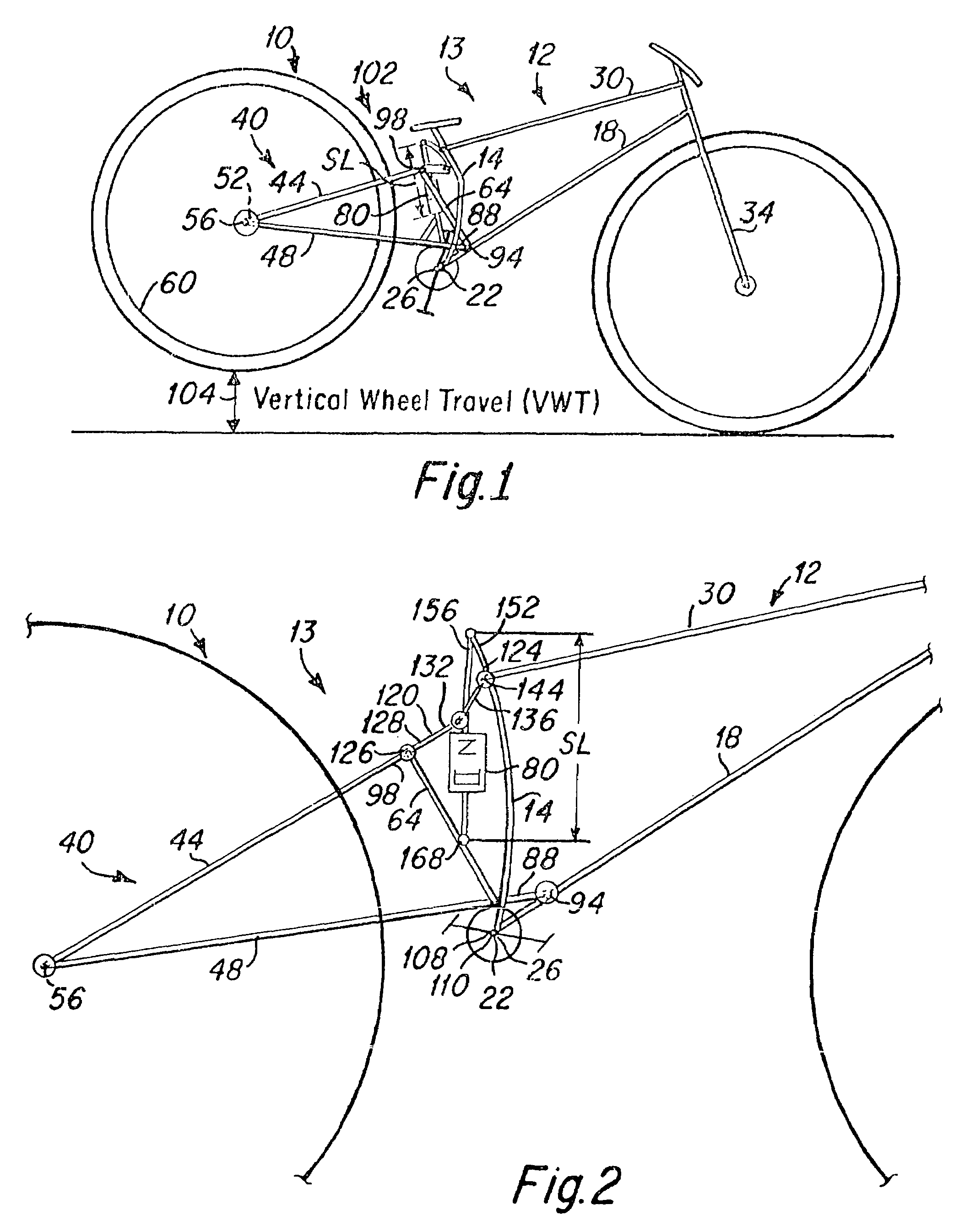
[0032]FIG. 1 depicts a rear wheel suspension system 10 engaged with a bicycle frame 12 of a bicycle 13 of the present invention. The bicycle frame 12 generally includes a seat tube 14 and a down tube 18, both of which are attached to a bottom bracket 22 that houses a pedal assembly 26, a top tube 30, and a front fork 34. These elements are typically welded or otherwise secured together to define the frame 12 of the bicycle. Although the frame 12 typically includes all of the foregoing members, alternative embodiments can have more or less than all of the foregoing members, and can include them in various forms, sizes, and configurations, and still achieve the intended functionality and beneficial aspects of the invention.

[0033]The rear wheel suspension system 10 generally includes a rear wheel swingarm 40 that includes a pair of seat stays 44 and a pair of chain stays 48 that are joined to each other at their rearward ends 52 proximate the axle 56 of the rear wheel 60. A pair of fro...

embodiment 13

[0034]In the bicycle embodiment 13 depicted in FIG. 1, the lower frontward end of the swingarm structure 40, proximate the frontward end 88 of the chain stays 48, is pivotally attached utilizing a pivot pin 94 or the like to the bicycle frame 12 proximate the bottom bracket 22, such that the swingarm rotates about the single pivot axis 94. The upper end of the swingarm, proximate the frontward end 98 of the seat stays 44 is engaged through a linkage structure 102 to the bicycle frame proximate the joinder of the seat tube 14 and top tube 30. The shock absorber 80 is engaged with the linkage to control the motion of the swingarm. A detailed description of the shock absorber engagement with the swingarm linkages and the controlled motion of the swingarm is also provided herebelow with the aid of FIG. 2.

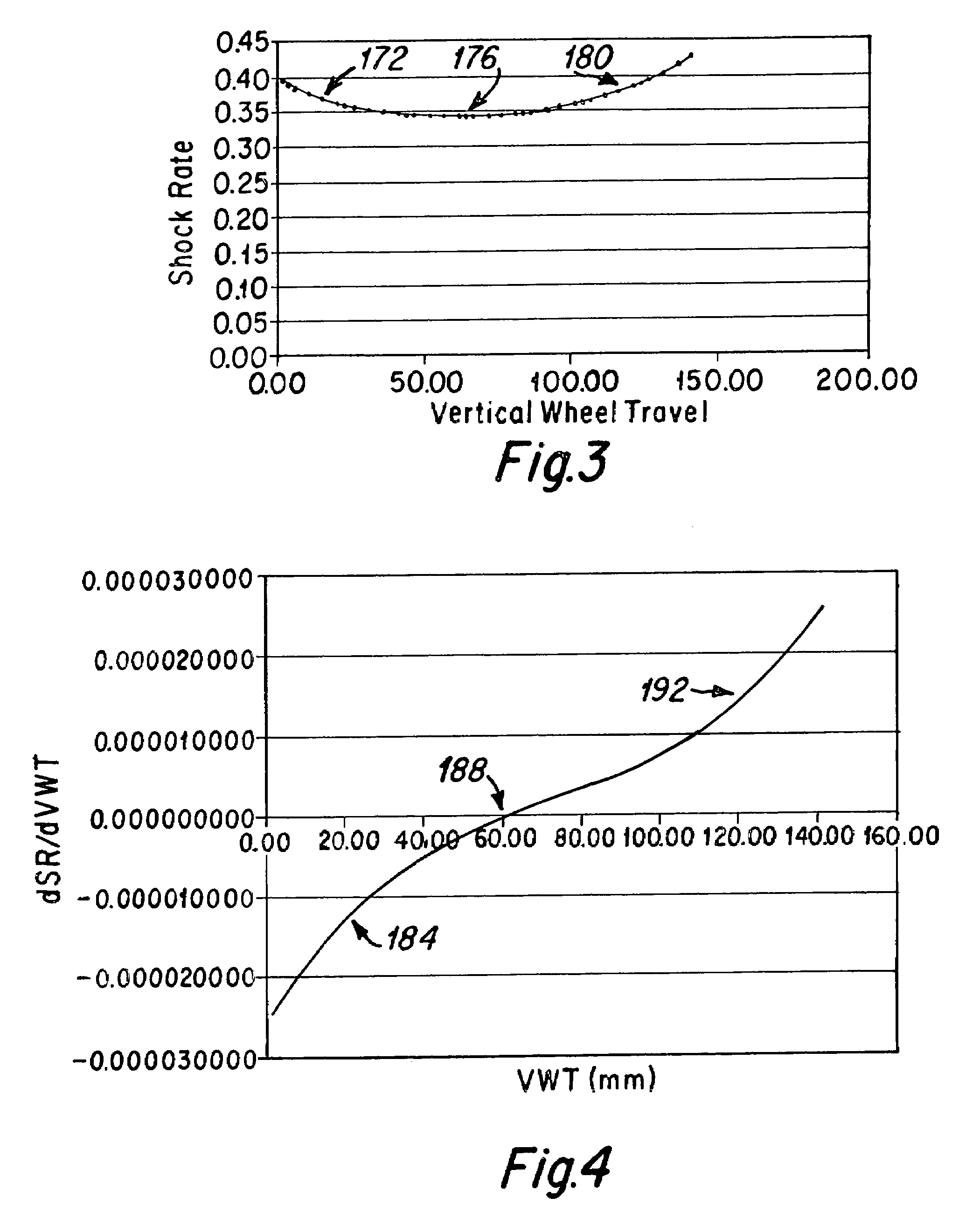
[0035]When the bicycle depicted in FIG. 1 is utilized, the rear wheel is designed to move generally vertically upward 104 about the single pivot axis 94 when the rear wheel encounters a...

embodiment 400

[0061]FIG. 10 is a schematic diagram showing another bicycle embodiment 400 of the present invention using a suspension system 402 that moves the rear wheel axle 404 via a swingarm 408 connected to a pair of linkages 412 and 416 that are each pivotally attached at one end to the swingarm 408, and pivotally attached at a second end to the mainframe 420 of the bicycle 400; FIG. 11 is an enlarged depiction of the bicycle 400 depicted in FIG. 10. The frame 420 includes the seat tube 14, down tube 18, and top tube 30, and the swingarm 408 includes seat stays 444, chain stays 448 and front stays 464. The swingarm motion is resisted by a shock absorber 424, such that the shock rate SR varies with vertical wheel travel, and the rate of change of the shock rate dSR / dVWT has a change in sign during the vertical wheel travel, as has been described above.

[0062]As is best seen in FIG. 11, the lower linkage 412 includes a connecting link 430 that is pivotally attached at its rearward end 432 to t...


PUM


Abstract

The present invention is a bicycle including a bicycle frame and a rear wheel suspension system that is attached to the frame. The rear wheel suspension system includes a rear wheel swingarm and a shock absorber that is engaged to the swingarm to control the motion of a rear wheel of the bicycle. A change in the vertical wheel travel (ΔVWT) of the rear wheel is related to a change in the length of the shock absorber (ΔSL), providing a shock rate (SR) according to the relationship:SR=ΔSL / ΔVWT. The shock rate (SR) changes throughout the vertical wheel travel of the rear wheel, such that the change in the shock rate dSR / dVWT has a change in sign as the rear wheel travels through its vertical wheel travel. The shock rate may at first decrease in value and subsequently increase, or initially increase in value and subsequently decrease throughout the vertical wheel travel of the rear wheel. In various exemplary embodiments the swingarm may be attached to the frame at a single pivot point or through a linkage system.

Description

BACKGROUND OF THE INVENTION[0001]1. Field of the Invention[0002]The invention generally relates to a shock absorbing rear wheel suspension apparatus for a bicycle, and more particularly to a rear wheel suspension having a controlled variable shock rate.[0003]2. Description of the Prior Art[0004]A variety of rear wheel suspension systems have been used on bicycles to improve performance. Many of these suspension systems are complicated structures involving a plurality of frame members, linkages of the swingarm frame members to other bicycle frame members and the installation of a shock absorber within the frame members to control the motion of the swingarm and the rear wheel engaged therewith.[0005]One such prior art suspension system is disclosed in U.S. Pat. No. 6,361,059 which describes a bicycle with a rear wheel suspension having a single pivot axis that is located proximate the bottom bracket of the bicycle frame. A top portion of the swingarm, proximate the seat stays, is enga...

Claims


Application Information

Patent Timeline
Patent Type & Authority Patents(United States)
IPC IPC(8): B62K1/00
CPCB62K25/286
Inventor GRANEY, JOSEPH E.
Owner SANTA CRUZ BICYCLES
Why Eureka
Try Eureka