Lens and LED using the lens to achieve homogeneous illumination

a technology of led and lens, applied in the field of led with homogeneous illumination, can solve the problem of insufficient optical energy transmitted to the central part by virtue of total reflection

Active Publication Date: 2009-09-01
IND TECH RES INST
View PDF11 Cites 56 Cited by
  • Summary
  • Abstract
  • Description
  • Claims
  • Application Information

AI Technical Summary

Benefits of technology

[0006]In view of the foregoing, an object of the invention is to provide a lens and a homogeneously illuminating LED using the lens. The invention can provide a large-area, homogeneous light-emitting surface. It can be directly used in a surface plane light source system. It further reduces the use of LED's to save the cost.
[0007]To achieve the above object, the disclosed lens and the LED that uses the lens have a lens designed on an action surface and in such a way that a concave divergent surface is formed around the optical axis. This design can deflect the light emitted in the vicinity of the optical axis away from the optical axis, so that the LED can provide a homogeneous and large-area light-emitting surface. According to a first embodiment, the invention includes a substrate, an LED chip, and a lens. The lens is bonded onto the substrate by packaging and covers the LED chip. The lens has a divergent surface around the optical axis and an adjacent convergent surface. The divergent surface diverges the light around the optical axis, and the convergent surface converges light of large angles toward the optical axis. Thus, the LED's can provide more homogeneous light in a larger area.

Problems solved by technology

Therefore, the optical energy transmitted to the central part by virtue of total reflections become insufficient as the area enlarges.
Nevertheless, the design relies on the total reflection and refraction of light.

Method used


Image

  • Lens and LED using the lens to achieve homogeneous illumination
  • Lens and LED using the lens to achieve homogeneous illumination
  • Lens and LED using the lens to achieve homogeneous illumination

Examples


first embodiment

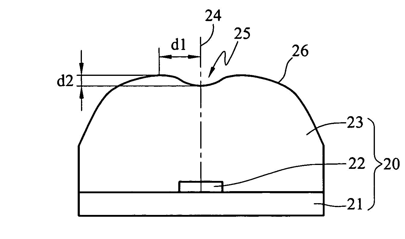
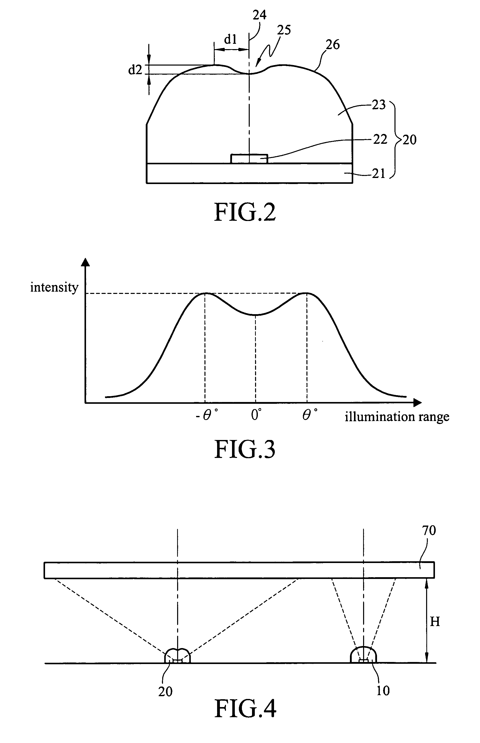
[0023]In observation of the fact that the conventional LED usually has stronger light intensity around its optical axis, the disclosed lens and the LED using the disclosed lens diverge light in the vicinity of the optical axis. the invention is shown in FIGS. 2 and 3. It contains a substrate 21, an LED chip 22, and a lens 23. The LED chip 22 is installed on the substrate 21 and has an optical axis 24. The lens 23 is connected to the substrate 21 by packaging to cover the LED chip 22. On the surface of the lens 23 and in the vicinity of the optical axis 24 is formed with a concave part as a divergent surface 25. The divergent surface 25 is surrounded by a convergent surface 26 with the optical axis 24 as a center. The divergent surface 25 is recessed towards the optical axis 24. The height difference from the divergent surface 25 to the bottom of the LED chip 22 increases from the optical axis outwards. The height difference from the convergent surface 26 to the bottom of the LED chi...

second embodiment

[0031]On the other hand, the invention is shown in FIG. 5. The lens 30 is designed to be a mask. Its surface also has a divergent surface 32 and a convergent surface 33. Its bottom has a concave part 31 that is greater than the LED chip 22. When the lens 30 is connected to the substrate 21, the concave part 31 covers the LED chip 22. A large-area homogeneous light-emitting area is also obtained.

third embodiment

[0032]the invention is shown in FIG. 6. The concave part 31 is designed according to the shape of the LED 10 so that it can be directly combined with a conventional LED 10. This design is more convenient in use. However, the light-emitting efficiency is slightly lower due to the extra deflection.


PUM


Abstract

A lens and an LED using the lens to achieve homogeneous illumination include a region. The region around the optical axis of a lens is designed to be concave and form a divergent surface. The upper surface of the lens is a continuous curved surface to diverge the high-intensity light emitted by the LED in the vicinity of the optical axis through refractions. Therefore, the LED can homogeneously illuminate a larger area.

Description

BACKGROUND OF THE INVENTION[0001]1. Field of Invention[0002]The invention relates to a lens and a light-emitting diode (LED) using the lens for illumination systems and, in particular, to an LED with homogeneous illumination.[0003]2. Related Art[0004]A traditional LED 10 is shown in FIG. 1A. It is formed by packing an LED chip 12 in a lens 11. The most commonly seen embodiment of the lens is illustrated in the drawing. The lens 11 is a hemisphere to converge the light emitted by the LED chip 12. The radiation pattern (directions and energy distribution of the emitted light) has to be restricted in the vicinity of the optical axis 13. Since the energy is more concentrated, one has to rely on the use of a light-guiding plate 14 to improve the homogeneity in the case of a surface plane light source. However, if the LED's 10 are directly distributed under the light-guiding plate, it requires a fair amount of LED's 10 because each one of them has a very small illuminating area. Therefore...

Claims


Application Information

Patent Timeline
Patent Type & Authority Patents(United States)
IPC IPC(8): H01L29/06H01L33/54H01L33/58
CPCG02B3/04G02B3/08G02F1/133606G02B19/0009G02B19/0014G02B19/0061H01L33/54G02B27/0955G02F1/133603G02F2001/133607H01L33/58G02F1/133607
Inventor HUANG, TIEN-FUSU, CHE-WEIHU, KUO-CHANG
Owner IND TECH RES INST
Why Eureka
Try Eureka