
Piezoelectric vibrator

a technology of vibrators and piezoelectrics, applied in piezoelectric/electrostrictive/magnetostrictive devices, piezoelectric/electrostriction/magnetostriction machines, impedence networks, etc., can solve the problem that the third harmonic overtone of the thickness shear mode cannot be trapped, and achieve the effect of increasing its siz

Inactive Publication Date: 2009-09-01
MURATA MFG CO LTD
View PDF33 Cites 0 Cited by
  • Summary
  • Abstract
  • Description
  • Claims
  • Application Information

AI Technical Summary

Benefits of technology

The patent text describes a piezoelectric ceramic resonator that can use the third harmonic overtone of the thickness shear vibration mode. This mode is trapped in a piezoelectric ceramic substrate with a reduced thickness, which decreases its mechanical strength. The text proposes a solution to this problem by providing an energy-trapping piezoelectric vibration portion that can trap the vibration energy of the third harmonic overtone. The text also discusses the resonance characteristic of the thickness shear vibration mode and the difficulty of trapping the third harmonic overtone in the piezoelectric vibration region where the excitation electrodes overlap. The technical effect of this patent is to provide an improved piezoelectric ceramic resonator that can use the third harmonic overtone of the thickness shear vibration mode while maintaining its mechanical strength.

Problems solved by technology

However, unlike the fundamental wave, there is a problem that the third harmonic overtone of the thickness shear mode cannot be trapped in a piezoelectric vibration portion where excitation electrodes overlap one another through a piezoelectric ceramic substrate.

Method used


Image

  • Piezoelectric vibrator
  • Piezoelectric vibrator
  • Piezoelectric vibrator

Examples


first embodiment

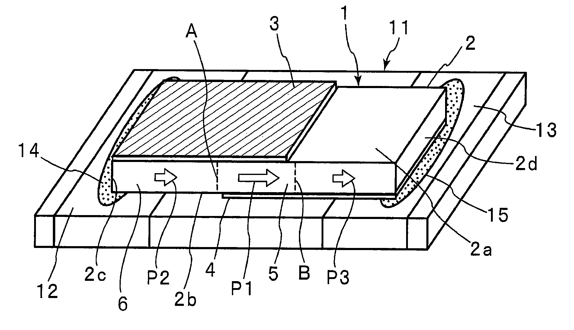
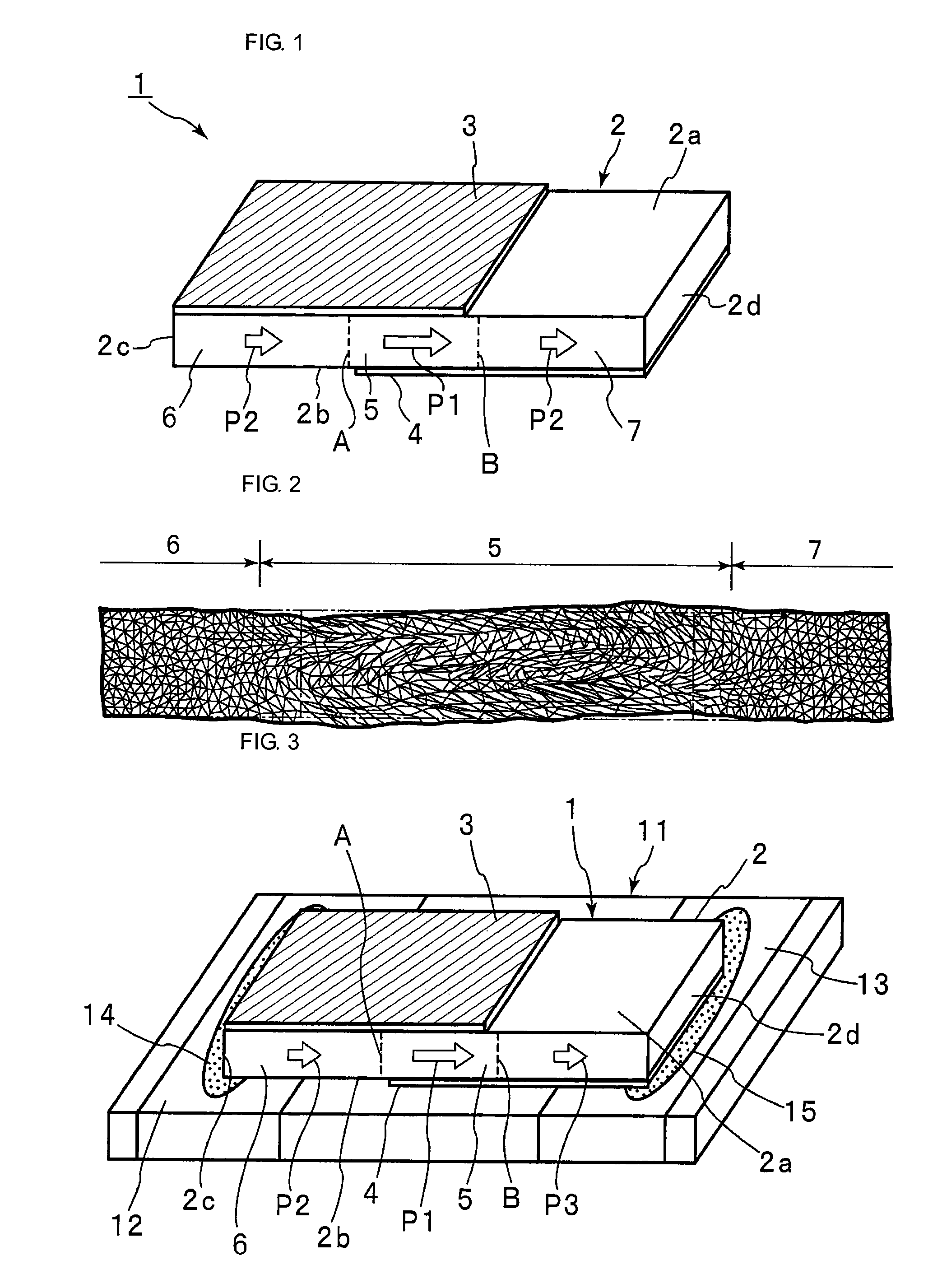
[0114]FIG. 1 is a perspective view showing a piezoelectric vibrator according to the present invention.

[0115]A piezoelectric vibrator 1 includes a strip piezoelectric ceramic substrate 2. Although the piezoelectric ceramic substrate 2 is composed of an appropriate piezoelectric ceramics, it is composed of a PZT piezoelectric ceramics in this embodiment.

[0116]The piezoelectric ceramic substrate 2 has an upper face 2a and a lower face 2b as first and second principal surfaces facing each other. In addition, the upper face 2a and the lower face 2b have a rectangular shape, which has a length direction and a width direction.

[0117]As shown by illustrated arrows P1 and P2, the piezoelectric ceramic substrate 2 is polarized in the length direction. More specifically, as shown by the arrow P1, a substantial length-direction central portion of the piezoelectric substrate 2 is intensely polarized in the length direction. The substantial central portion sandwiched by broken lines A and B const...


PUM

PropertyMeasurementUnit
sizeaaaaaaaaaa
sizeaaaaaaaaaa
lengthaaaaaaaaaa

Abstract

An energy-trapping strip piezoelectric vibrator utilizing a third harmonic overtone of a thickness shear mode is provided. A piezoelectric vibrator 1 has a strip piezoelectric ceramic substrate 2 polarized in a longitudinal direction, and first and second excitation electrodes 3 and 4 provided on first and second principal surfaces 2a and 2b of the piezoelectric ceramic substrate 2. An excitation region 5 including a piezoelectric vibration portion that includes a portion where the first and second excitation electrodes 3 and 4 overlap and that utilizes harmonics of the thickness shear mode is formed. A region around the piezoelectric vibration portion is set as a non-excitation region. At least a region of the non-excitation region neighboring the piezoelectric vibration portion is a region having the same polarization axis direction as the excitation region 5 and a relatively small polarization degree or is an unpolarized region.

Description

[0001]This is a continuation of application Serial Nos. PCT / JP2006 / 325395, filed Dec. 20, 2006 and PCT / JP2007 / 051289, filed Jan. 26, 2007.TECHNICAL FIELD[0002]The present invention relates to piezoelectric vibrators utilizing a thickness shear vibration mode. More particularly, the present invention relates to an energy-trapping piezoelectric vibrator that is constituted using a piezoelectric ceramic substrate and that utilizes a third harmonic overtone of the thickness shear vibration mode.BACKGROUND ART[0003]Conventionally, piezoelectric ceramic resonators utilizing a basic thickness shear vibration mode have been widely used as resonators in the band of 3.5-12 MHz. Such piezoelectric ceramic resonators utilizing the basic thickness shear vibration mode are disclosed in various documents regarding the related art, such as Patent Document 1.[0004]FIG. 34 is a perspective view showing a conventional piezoelectric ceramic resonator utilizing a fundamental wave of a thickness shear vi...

Claims


Application Information

Patent Timeline
Patent Type & Authority Patents(United States)
IPC IPC(8): H01L41/08H01L41/09H01L41/187H01L41/22H01L41/257H03H3/02H03H9/17
CPCH03H9/0207H03H9/131H03H9/562H03H9/177Y10T29/42H03H9/02007H03H9/13H10N30/20H10N30/853
Inventor KAIDA, HIROAKIKANAI, SHUNGOSAKAGUCHI, HITOSHI
Owner MURATA MFG CO LTD
Learn More