High power bipolar pulse generators with impedance transformation

a generator and impedance technology, applied in pulse train generators, pulse techniques, line-transmission details, etc., can solve the problems of low efficiency of the first category when used to transform from mohm impedance to, for example, 50 ohm, and large size, so as to maximize energy transfer and efficient impedance transformation

Inactive Publication Date: 2009-09-01
BAE SYST INFORMATION & ELECTRONICS SYST INTERGRATION INC
View PDF8 Cites 10 Cited by
  • Summary
  • Abstract
  • Description
  • Claims
  • Application Information

AI Technical Summary

Benefits of technology

[0014]According to the present invention, bipolar pulse generators provide bipolar pulses and efficient impedance transformation. The circuits are amenable for implementation in a variety of configurations depending on the pulse power, preferable size and required pulse width. They also maximize energy transfer and may be implemented in a straightforward, easy manner.
[0016]According to another embodiment of the present invention, the bipolar pulse generator provides close to 1:4 impedance transformations, near the maximum energy on the load, and is suitable for a further efficient impedance transformation. It includes the inductive stub, which does not deteriorate the pulse shape.
[0019]According to still another embodiment of the present invention, a bipolar pulse generator is matched with transmission line transformer in a way that inductive stub of the transformer does not deteriorate pulse shape.

Problems solved by technology

For bipolar pulse generators having transmission lines with low characteristic impedances (in the mOhm range), a problem occurs when the generators are used to drive typical load impedances, such as 50 Ohm or higher.
In general, transformers of first category when used to transform from mOhm impedances to, for example 50 Ohms, generally have low efficiency, large size and are also difficult to fabricate.
Therefore, these transformers themselves can defeat some of the advantages of having high efficiency, high powered and high energy density transmission line bipolar pulse generators.
Lower characteristic impedance implies less dielectric thickness between the line's conductors and, therefore, a higher electric field, which is a limitation for selected charging voltage defined by the chosen switch.

Method used


Image

  • High power bipolar pulse generators with impedance transformation
  • High power bipolar pulse generators with impedance transformation
  • High power bipolar pulse generators with impedance transformation

Examples


Embodiment Construction

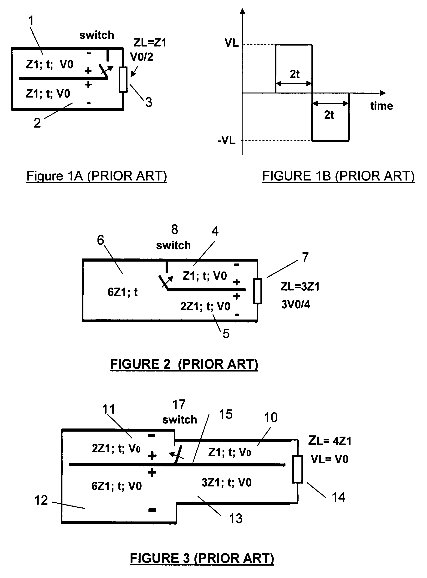
[0043]FIG. 1(a) illustrates a schematic of a well-known bipolar pulse generator (A. I Pavlovskii et al in Soviet Phys. Dokl. V.20, 1975). A modification of this generator was presented in U.S. Pat. No. 4,536,723. In this generator, with a closing switch, the impedance ZL of matched load 3 is equal to the characteristic impedance Z1 of the two equally charged transmission lines 1 and 2, and voltage on the load is equal to ½ of the charged voltage of the transmission lines.

[0044]This is the best case with respect to two factors, energy and efficiency. However, this generator provides no impedance transformation to a load 3, having the same impedance Z1. The total stored energy in the generator is twice the energy stored in each transmission line, and all the stored energy is transferred to the bipolar pulse illustrated on FIG. 1(b) for the ideal case when both transmission lines are lossless and the switch is ideal.

[0045]Modern, fast rise time, photo-conductive switches (operating in ...


PUM


Abstract

A bipolar pulse generator circuit generates bipolar pulses and provides an impedance transformation. The circuit is amenable for implementation in a variety of configurations depending on the size and pulse width requirements for the design. It also maximizes energy transfer and may be implemented in a straight forward, easy manner.The generator may be implemented with one or two switches in a three, five or more transmission line implementation and may include inductive stub, which is inherent element of transmission line transformers. The generator may also be implemented in a multi-layer folded configuration, with or without the addition of a ground potential conductor. The generator may also be implemented in stacked or / and balanced configurations.

Description

FIELD OF THE INVENTION[0001]The present invention relates generally to bipolar pulse generators, particularly to the high power bipolar pulse generators that provide impedance transformation.BACKGROUND OF THE INVENTION[0002]Modern trends in High Power Microwave (HPM) sources for a variety of applications are directed towards increasing radiated power and efficiency in order to increase energy density (energy per volume). Transmission line type pulse generators with photoconductive switches can achieve some of the best results. In particular, they are compact and provide fast pulse rise time, high power, and are suitable for generating short pulses (nanoseconds range) with perfect shape.[0003]For a given charging voltage for transmission lines, limited by electric field in photoconductive switches, high powered and high energy density transmission lines imply low characteristic impedances. For bipolar pulse generators having transmission lines with low characteristic impedances (in t...

Claims


Application Information

Patent Timeline
Patent Type & Authority Patents(United States)
IPC IPC(8): H04B3/04
CPCH04L25/0278
Inventor LONDON, SIMON Y.
Owner BAE SYST INFORMATION & ELECTRONICS SYST INTERGRATION INC
Why Eureka
Try Eureka