A fuel activation and energy release apparatus, system and method thereof

a technology of fuel activation and energy release, which is applied in the direction of engine ignition, fuel treatment, chemical/physical/physicochemical processes, etc., can solve the problems of excessive fuel consumption of engines employing conventional gas and diesel fuel, insufficient fuel efficiency burning of such engines, and insufficient fuel efficiency of such engines, so as to reduce the emission of exhaust gases, increase the amount of energy, and reduce the effect of fuel consumption

Active Publication Date: 2018-06-07
ARCS ENERGY LTD
View PDF4 Cites 0 Cited by
  • Summary
  • Abstract
  • Description
  • Claims
  • Application Information

AI Technical Summary

Benefits of technology

[0012]The apparatus provides the advantage that the energy state of the injected fluid substance (e.g. free radicals gas) is increased by the “coupling” electromagnetic radiation (i.e. the predetermined wavelength of the electromagnetic radiation is matched to the electron energy state of the free radicals), therefore providing a highly reactive substance adapted to release a significantly increased amount of energy that can be utilised, for example, to provide work (e.g. via a turbine). In addition, the highly reactive substance is further adapted to minimise any potential emission exhaust when being combusted. Alternatively, the apparatus of the present invention may be utilised in existing combus

Problems solved by technology

However, while the employment of combustion engines has significantly increased the industrial output, it is certainly not without detriment.
However, the burning of fuel in such engines is never completely efficient and as a consequence, engines employing conventional gas and diesel fuel suffer fro

Method used


Image

  • A fuel activation and energy release apparatus, system and method thereof
  • A fuel activation and energy release apparatus, system and method thereof
  • A fuel activation and energy release apparatus, system and method thereof

Examples


Embodiment Construction

)

[0043]Exemplary embodiments of this invention will be described in relation to an energy source generator and a system adapted to improve fuel efficiency, both of which are retrospectively fittable with the apparatus of the present invention. However, it will be appreciated by the person skilled in the art that the apparatus and system of the present invention may be utilised with any suitable energy conversion or power generation system.

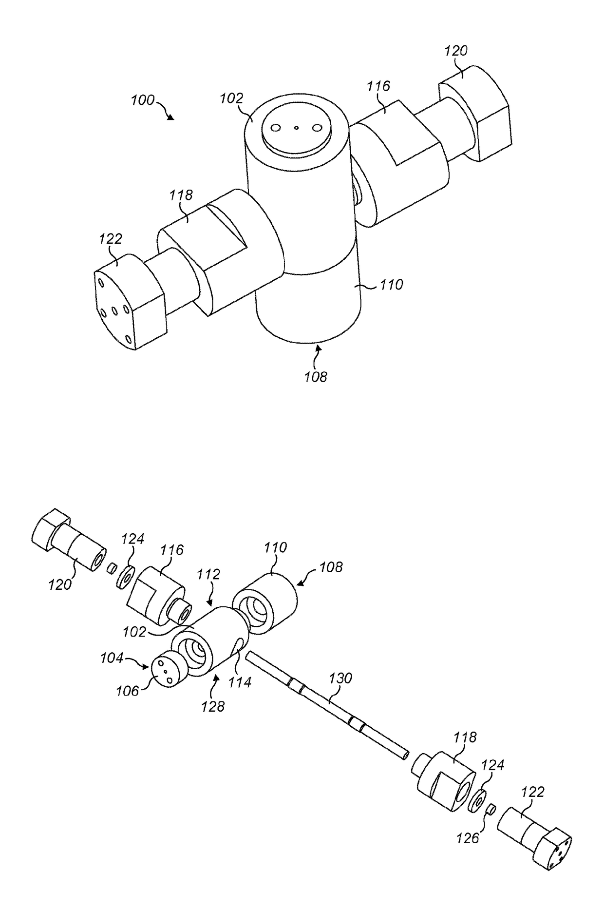
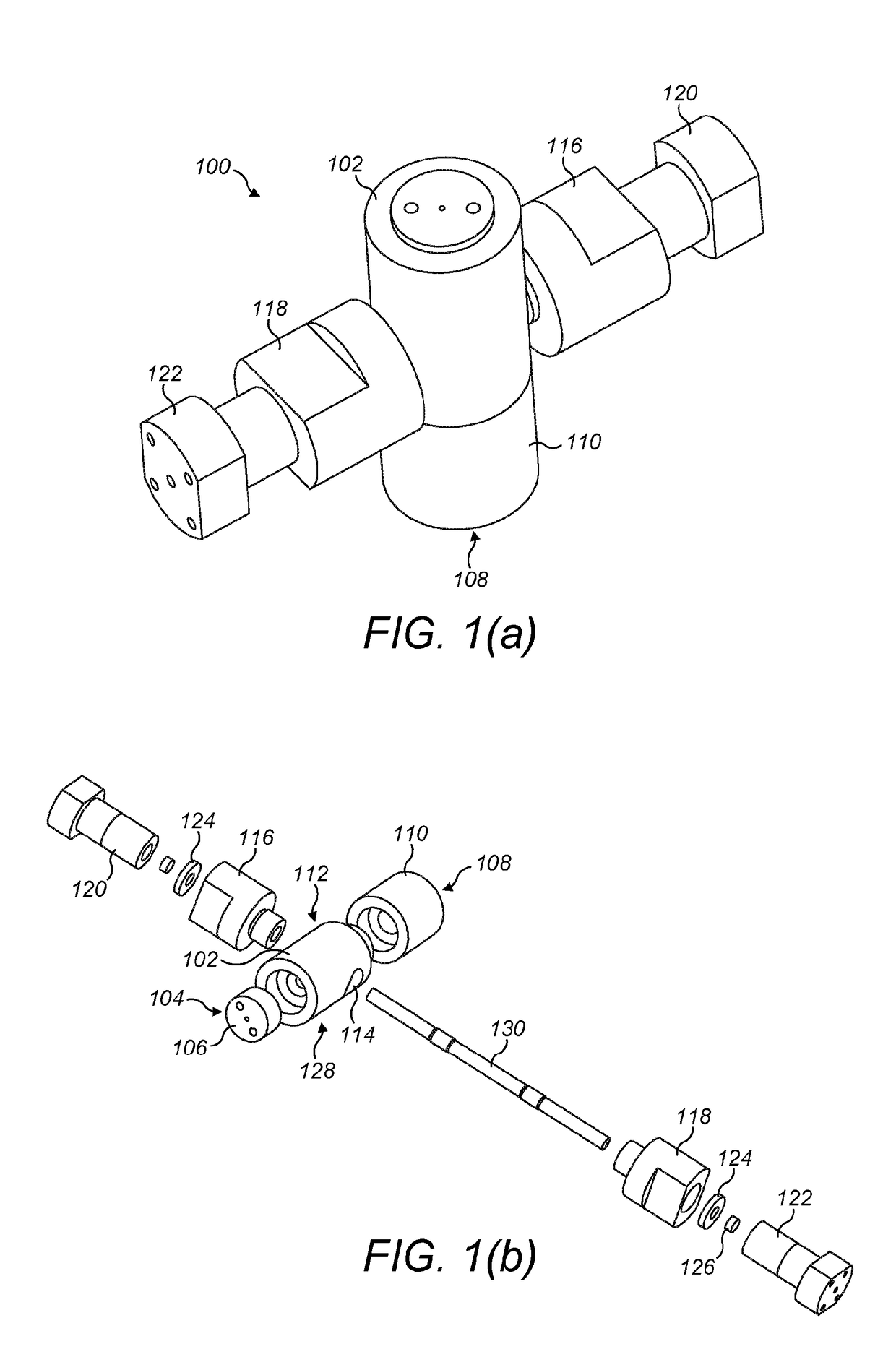
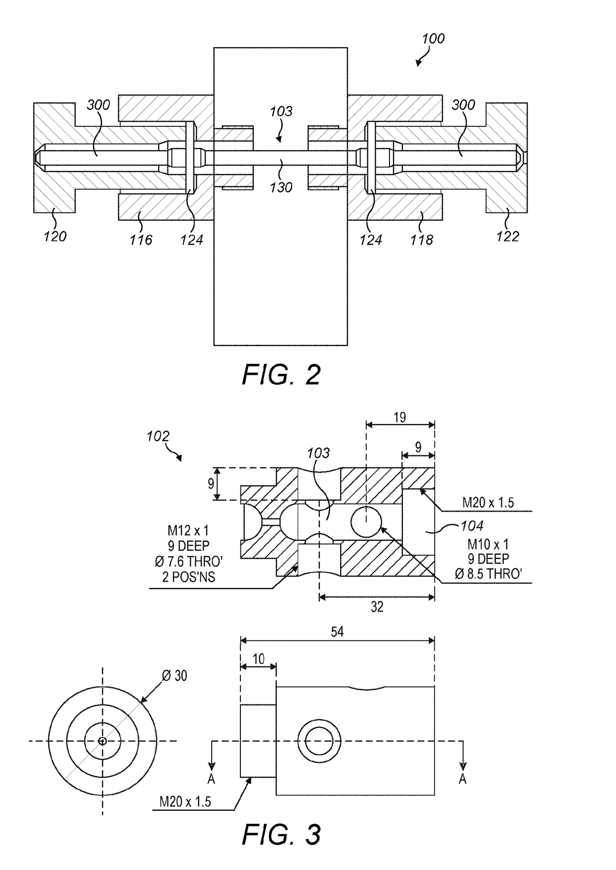
[0044]Referring now generally to FIGS. 1 to 10, an example embodiment of the main reactor unit 100 of the present invention comprises a main body 102 having a central reactor chamber 103, an injection port 104, including an end cap 106 that is screwed into an opening of the injection port 104, and an ejection port 108, including a gas coupler 110 that is connected to the ejection port 108 (e.g. screw fit). The main body 102 further comprises access ports 112 and 114 adapted to receive and mount EMR input members 116 and 118. Two EMR couplers 120 an...


PUM


Abstract

A fuel activation and energy release apparatus is provided for increasing energy output of a fluid substance. The apparatus comprises a fluidly sealable reactor chamber, adapted to withstand a predetermined fluid pressure and temperature; a fluid injection port, adapted to provide a one-way fluid communication from an external fluid reservoir to said reactor chamber; a fluid ejection port, adapted to provide a one-way fluid communication from said reactor chamber to an external region, so as to controllably release said fluid substance from said reactor chamber and at least one first electromagnetic radiation (EMR) waveguide. The first EMR waveguide having a first waveguide input port and a first waveguide output port, operably coupled within said reactor chamber and adapted to couple electromagnetic radiation of a predetermined first wavelength to a fluid substance injected into said reactor chamber.

Description

[0001]The present invention relates generally to the field of energy generation and improvement in fuel efficiency, as well as, reduction of harmful emissions. In particular, the present invention relates to an apparatus for improved energy release from any fluid substance.INTRODUCTION[0002]The search for potent, dependable and sustainable energy sources is becoming increasingly urgent in order to provide for the ever-increasing demand for energy. The industrialized world has primarily evolved around the combustion engine, which is capable of providing mechanical energy to do work in a vast variety of circumstances. However, while the employment of combustion engines has significantly increased the industrial output, it is certainly not without detriment. For example, combustion engines run, for the most part, on fossil fuels such as gasoline and diesel fuel (i.e. hydrocarbons), which are primarily derived by the refinement of crude oil and which provide an easily transportable rese...

Claims


Application Information

Patent Timeline
IPC IPC(8): B01J19/12F02M27/04F02M31/02
CPCB01J19/126F02M27/04F02M31/02B01J19/128B01J2219/0004B01J2219/0877B01J2219/0875B01J2219/1215B01J2219/1227B01J2219/1239B01J2219/1269B01J2219/1293B01J2219/1254B01J2219/1272F02P23/045Y02T10/12B01J19/12B01J19/087
Inventor ARCHER, ANTHONY
Owner ARCS ENERGY LTD
Why Eureka
Try Eureka