Adhesive bonded attachment assembly for an insulation blanket

a technology of adhesive bonding and attachment assembly, which is applied in the direction of screws, furniture, lighting and heating apparatus, etc., can solve the problems of unfavorable thermal damage to the substrate and adjoining components, and achieve the effect of improving the heat-shielding of the gromm

Active Publication Date: 2009-09-08
PHYSICAL SYST
View PDF18 Cites 75 Cited by
  • Summary
  • Abstract
  • Description
  • Claims
  • Application Information

AI Technical Summary

Benefits of technology

[0006]In accordance with the invention, an improved adhesive bonded attachment assembly is provided for use in a high temperature operating environment, such as supporting and retaining an insulation blanket on a substrate such as aircraft engine nacelle or the like. The attachment assembly includes a stud attachment having an enlarged base defining a mounting surface for adhesive bonded affixation to the substrate, in combination with a fastener element such as a threaded stud extending from the base for at least partial reception into a grommet-lined mounting port formed in the insulation blanket. An insulated cap fastener is secured to the fastener element to retain the insulation blanket on the nacelle substrate in a manner shielding surrounding structures and components from heat generated during engine operation. The insulated cap fastener is sized to physically and thermally overlie the associated grommet for improved heat-shielding of the grommet and the adhesive bonded stud attachment, thereby safeguarding against debonding of the attachment base in response to high temperature exposure.

Problems solved by technology

Such failure of the stud attachment can undesirably expose the substrate and adjoining components to thermal damage.

Method used


Image

  • Adhesive bonded attachment assembly for an insulation blanket
  • Adhesive bonded attachment assembly for an insulation blanket
  • Adhesive bonded attachment assembly for an insulation blanket

Examples


Embodiment Construction

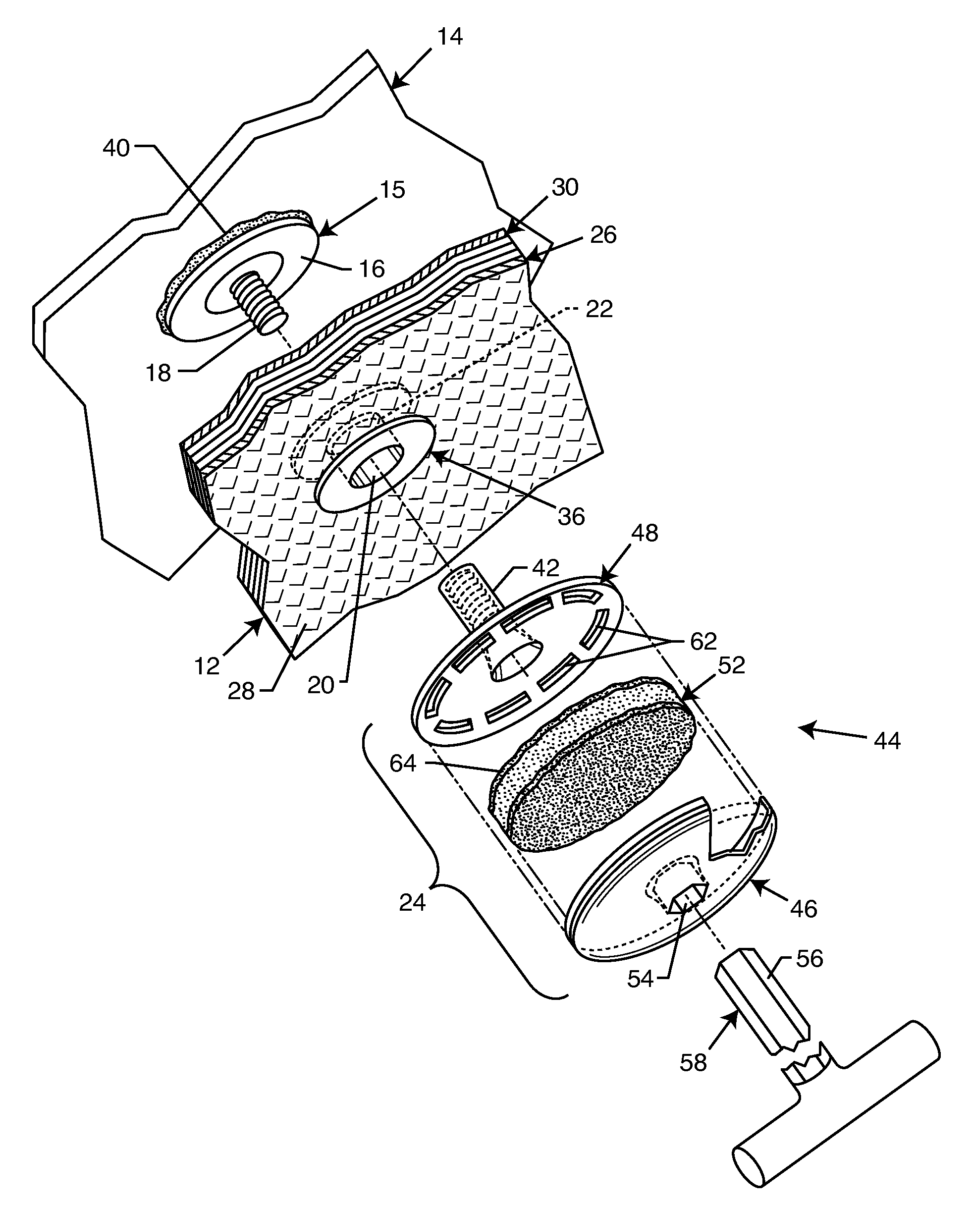
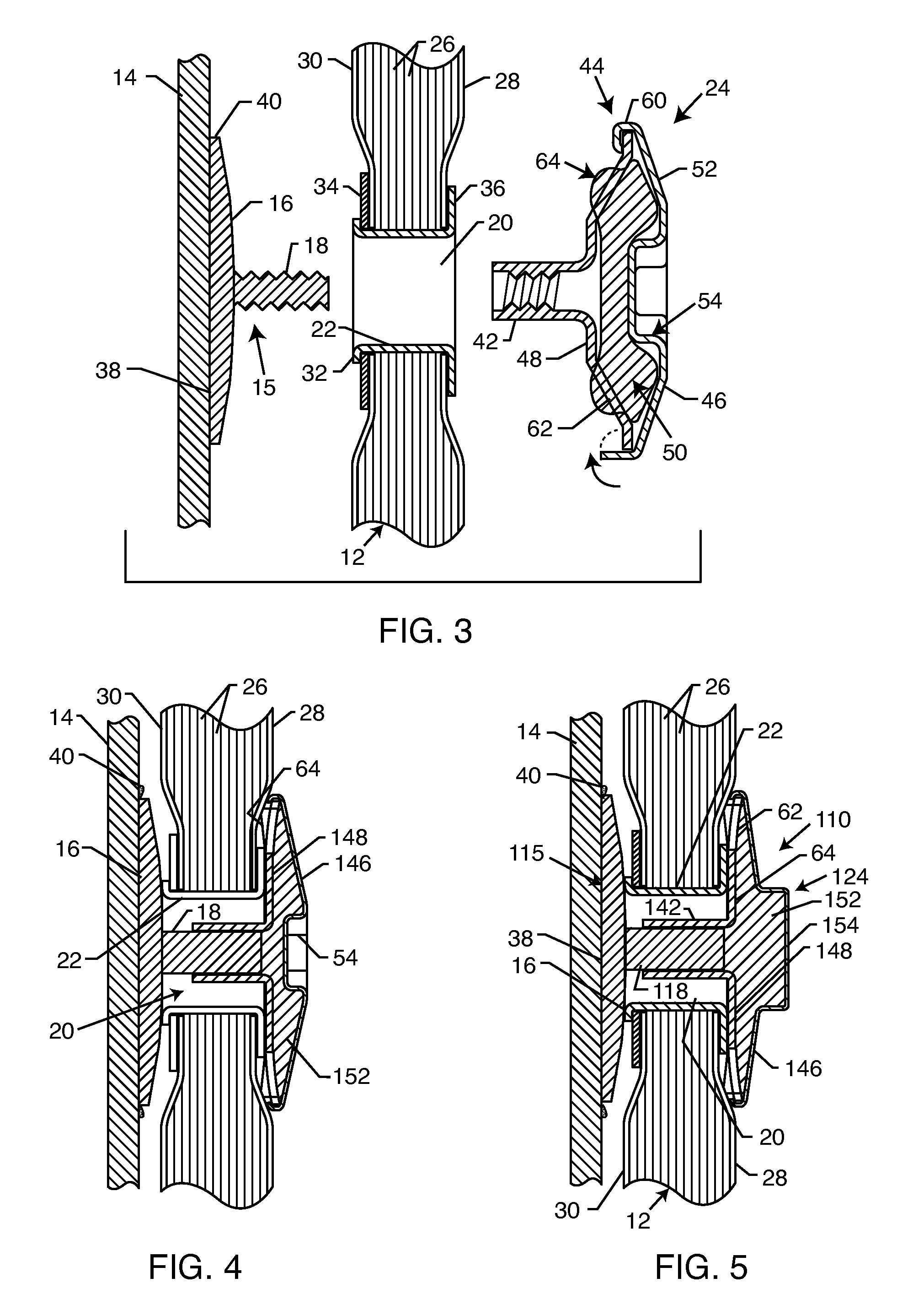
[0020]As shown in the exemplary drawings, an improved adhesive bonded attachment assembly referred to generally in FIG. 1 by the reference numeral 10 is provided for use in a relatively high temperature operating environment, such as for use in supporting and retaining an insulation blanket 12 on a substrate 14 such as an aircraft engine nacelle or the like. Multiple attachment assemblies 10 are provided each including an attachment member such as a stud attachment 15 (FIGS. 2 and 3) having a base 16 designed for secure bond-on attachment to the substrate 14, and a fastener element 18 such as a stud to fit within as associated mounting port 20 formed in the insulation blanket 12 and lined by a cylindrical grommet 22. Each attachment assembly 10 further includes an insulated cap fastener 24 assembled with the associated fastener element 18 to support and retain the blanket on the substrate 14. The insulated cap fastener 24 is constructed to overlie the associated mounting port 20 and...


PUM


Abstract

An adhesive bonded attachment assembly is provided for supporting and retaining an insulation blanket on a substrate such as aircraft engine nacelle or the like. The attachment assembly includes a stud attachment having a base for adhesive bonded affixation to the nacelle substrate and a fastener element such as a threaded stud extending from the base at least partially into a grommet-lined mounting port formed in the insulation blanket. A radially enlarged, insulated cap fastener is secured to the fastener element to retain the insulation blanket on the nacelle substrate in a manner shielding surrounding structures and components from heat generated during engine operation. The insulated cap fastener projects radially beyond the associated grommet for improved heat-shielding of the adhesive bonded stud attachment, thereby safeguarding against debonding of the attachment base in response to high temperature exposure.

Description

BACKGROUND OF THE INVENTION[0001]This invention relates generally to improvements in and to adhesive attachments of the type designed for bonded affixation to a selected substrate, such as an adhesive stud attachment of the general type disclosed in U.S. Pat. Nos. 4,778,702 and 4,842,912. More specifically, this invention relates to an improved attachment assembly for use in a high temperature environment, particularly such as supporting and retaining an insulation blanket or the like on a substrate such as an aircraft engine nacelle to shield surrounding structures and components from heat generated during engine operation. The improved attachment assembly includes an insulated cap fastener for safeguarding a stud attachment against debonding in response to high temperature exposure.[0002]Adhesive bonded attachments are generally known in the art for connecting a selected component such as a threaded stud or bolt onto a selected substrate such as a panel or other frame component in...

Claims


Application Information

Patent Timeline
Patent Type & Authority Patents(United States)
IPC IPC(8): E04B1/74E04B1/38E04B2/00E04B5/00E04B9/00E04C1/40
CPCB64C1/40B64C1/403F16B37/048F16B37/145Y10T428/24008F16B11/006
Inventor HUTTER, III, CHARLES G.
Owner PHYSICAL SYST
Why Eureka
Try Eureka