Tape feeder

a feeder and tape technology, applied in the field of tape feeders, can solve the problems of contaminating the operational environment, the inability to smoothly supply the chip, and the difficulty of loading the electronic components on the tray and mounting the same on the printed circuit board, so as to ensure the operation environment and ensure the smooth supply of electronic components

Inactive Publication Date: 2009-09-08
HANWHA AEROSPACE CO LTD
View PDF10 Cites 5 Cited by
  • Summary
  • Abstract
  • Description
  • Claims
  • Application Information

AI Technical Summary

Benefits of technology

[0014]In order to solve the foregoing and / or other problems, it is an aspect of the present invention to provide a tape feeder including an electronic component accommodating part installed at one side of a tape feeder main body to accommodate electronic components which are not picked up by a suction nozzle of an electronic component conveyance robot installed at an electronic component mounting device, to thereby smoothly perform a supply of the electronic components and keep an operational environment clean, and thus prevent the electronic components from clogging a carrier tape moving path.

Problems solved by technology

However, when the electronic components are small, it may be difficult to load the electronic components on the tray and mount the same on the printed circuit board.
In particular, when very small electronic components are mounted, since the electronic components may be frequently lost or damaged during operation, a specifically designed tape feeder may be used.
However, when it is not possible for the semiconductor chip to be discharged to the exterior of the tape feeder, thereby clogging progress of the carrier tape, the semiconductor chips may be stacked on a feeder base and a feeder attach / detach rail, on which the tape feeder is mounted, thus creating operational difficulties and causing misalignment of a pick-up position of the semiconductor chip, thereby contaminating an operational environment.
As a result, the semiconductor chip cannot be smoothly supplied, and further, the operational process may be delayed or stopped.

Method used


Image

  • Tape feeder
  • Tape feeder
  • Tape feeder

Examples


Embodiment Construction

[0028]Reference will now be made in detail to exemplary embodiments of the present invention, examples of which are illustrated in the accompanying drawings. The embodiments are described below in order to explain the present invention by referring to the figures.

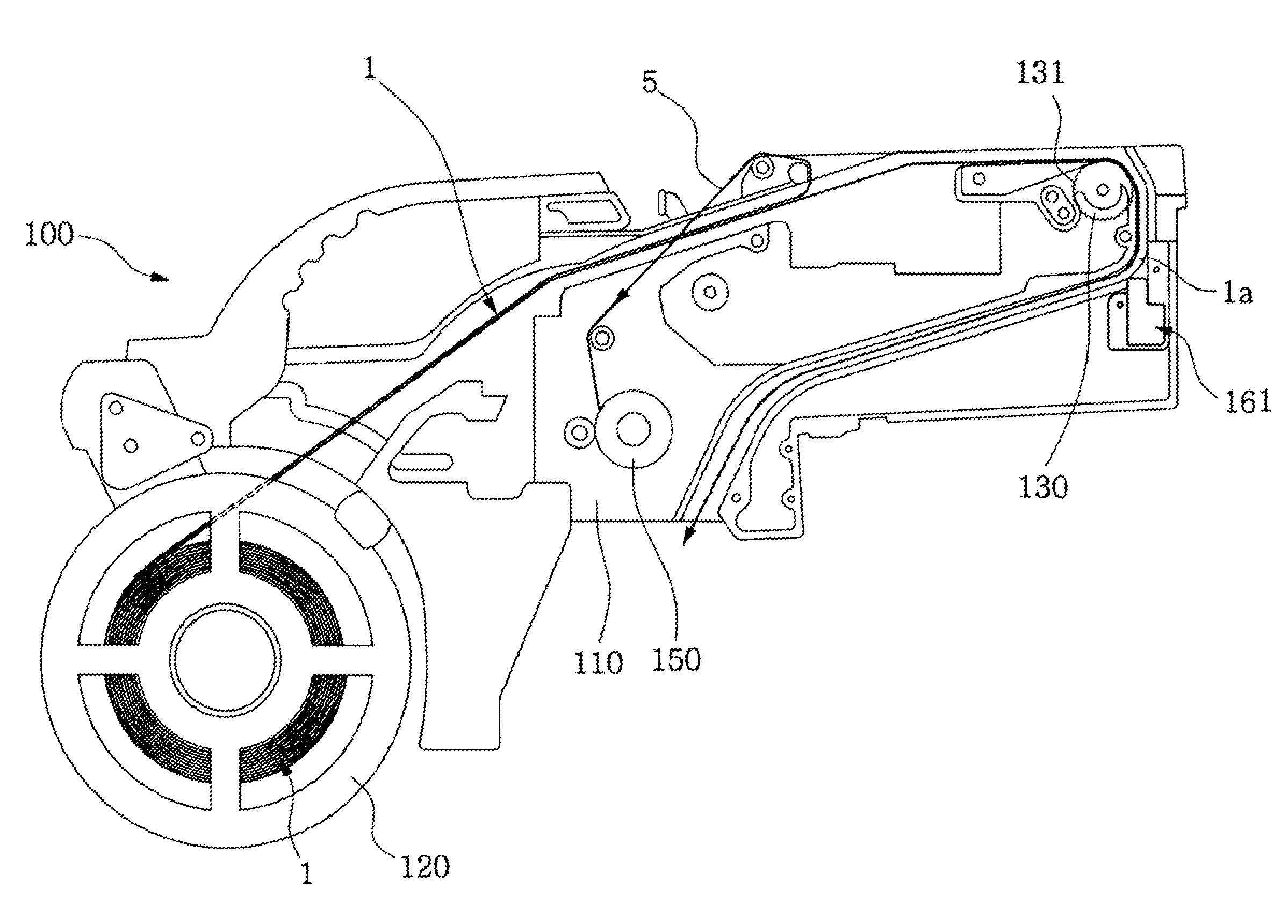
[0029]As shown in FIGS. 3 to 5, the tape feeder 100 in accordance with an exemplary embodiment of the present invention includes a tape reel 120 rotatably installed at one side of a tape feeder main body 110 and on which a carrier tape 1 is wound. A sprocket 130 is rotatably installed at another side of the tape feeder main body 110. Teeth 131 meshed with conveyance holes 6 of the carrier tape 1 are formed at an outer periphery of the sprocket 130. A collection part 150 is installed at another side of the tape feeder main body 110 to collect the cover tape 5 removed from the carrier tape 1.

[0030]An electronic component accommodating part 161, referred to as a dump box, is installed at another side of the tape feeder main bo...


PUM

PropertyMeasurementUnit
radiusaaaaaaaaaa
sizeaaaaaaaaaa
sizesaaaaaaaaaa

Abstract

A tape feeder including an electronic component accommodating part installed at one side of a tape feeder main body to accommodate electronic components which are not picked up by a suction nozzle of an electronic component conveyance robot installed at an electronic component mounting device, thereby preventing the electronic components from clogging a carrier tape moving path, and storing the electronic components in the electronic component accommodating part. Therefore, it is possible to increase efficiency of equipment without operational delay and stoppage of the equipment, readily extract and reuse the electronic components accommodated in the electronic component accommodating part, and keep an operational environment clean.

Description

CROSS-REFERENCE TO RELATED APPLICATION[0001]This application claims the benefit of Korean Patent Application No. 2007-0022394, filed Mar. 7, 2007, the disclosure of which is hereby incorporated herein by reference in its entirety.BACKGROUND OF THE INVENTION[0002]1. Field of the Invention[0003]The present invention relates to a tape feeder and, more particularly, to a tape feeder including an electronic component accommodating part installed at one side of a tape feeder main body to accommodate electronic components which are not picked up by a suction nozzle of an electronic component conveyance robot installed at an electronic component mounting device.[0004]2. Description of the Related Art[0005]Generally, an electronic component mounting device, referred to as a chip mounter, is an automated device used to mount electronic components such as semiconductor chips at a predetermined position on a printed circuit board. The various kinds of electronic components used in the electroni...

Claims


Application Information

Patent Timeline
Patent Type & Authority Patents(United States)
IPC IPC(8): B65H20/00B23P19/00
CPCB65H29/64B65H37/002H05K13/0084B65H2301/54Y10T29/49124Y10T29/53191Y10T29/5124B65H2701/1942H01L21/48H01L21/68
Inventor KIM, YOUNG-IL
Owner HANWHA AEROSPACE CO LTD
Why Eureka
Try Eureka