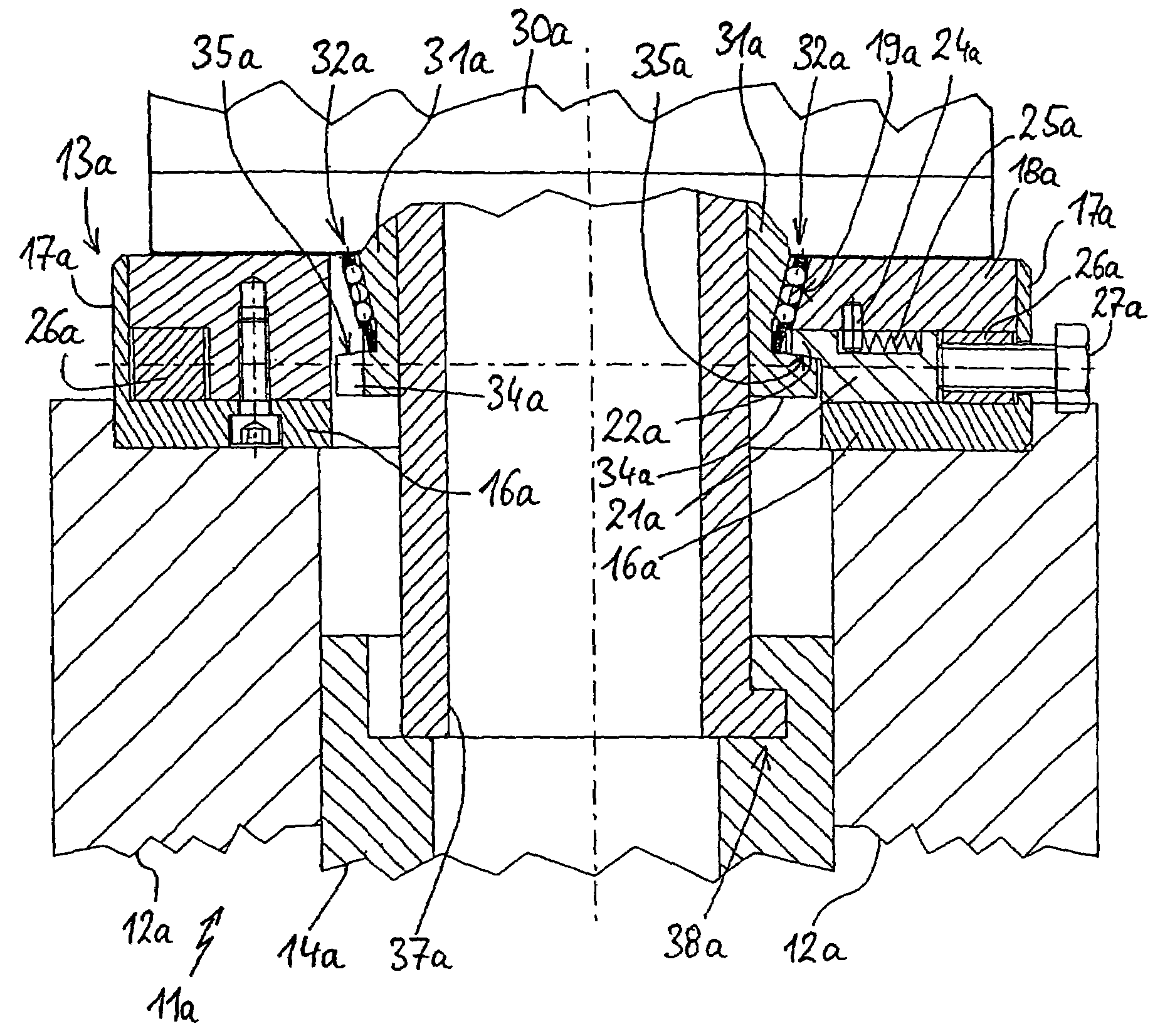
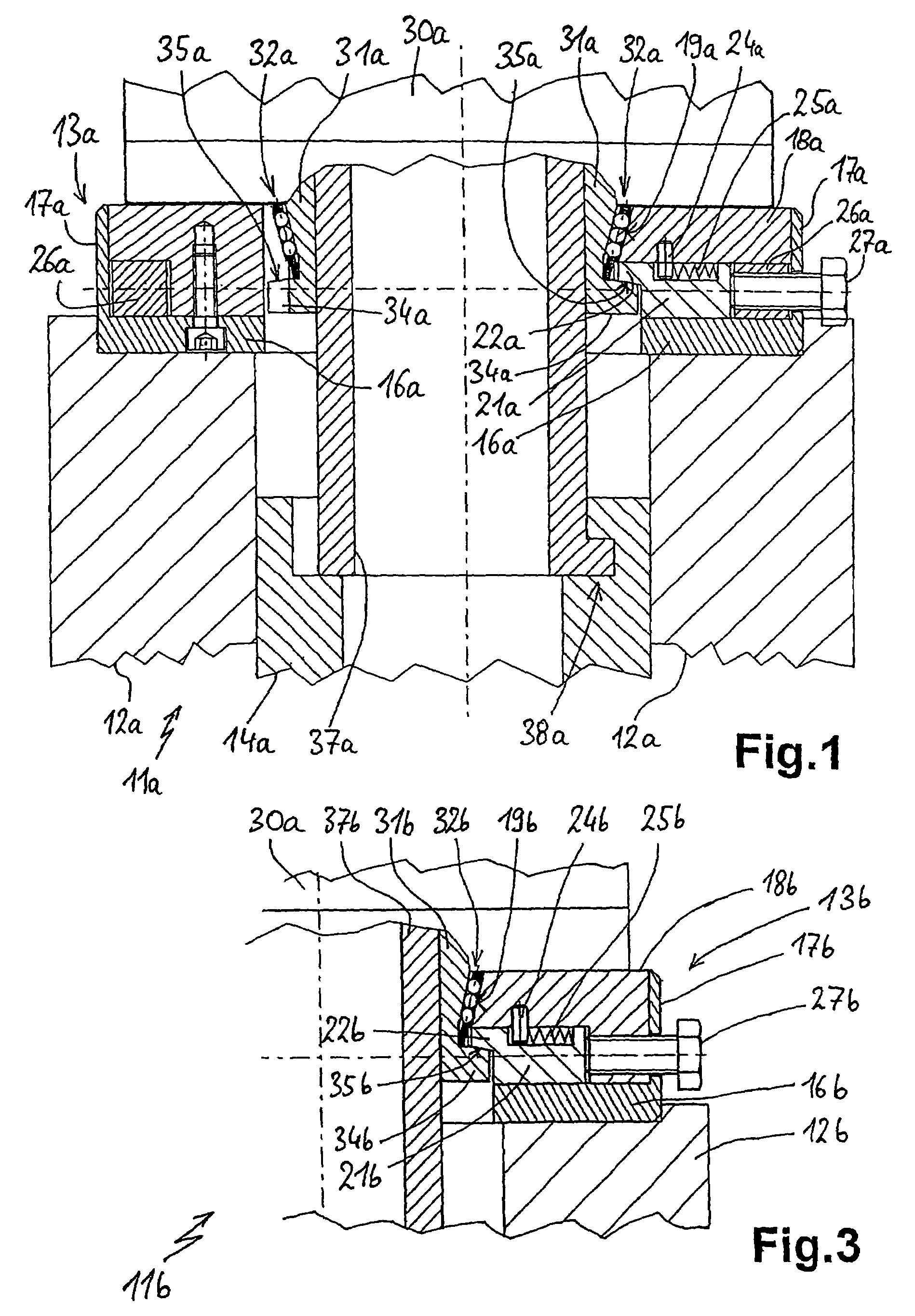
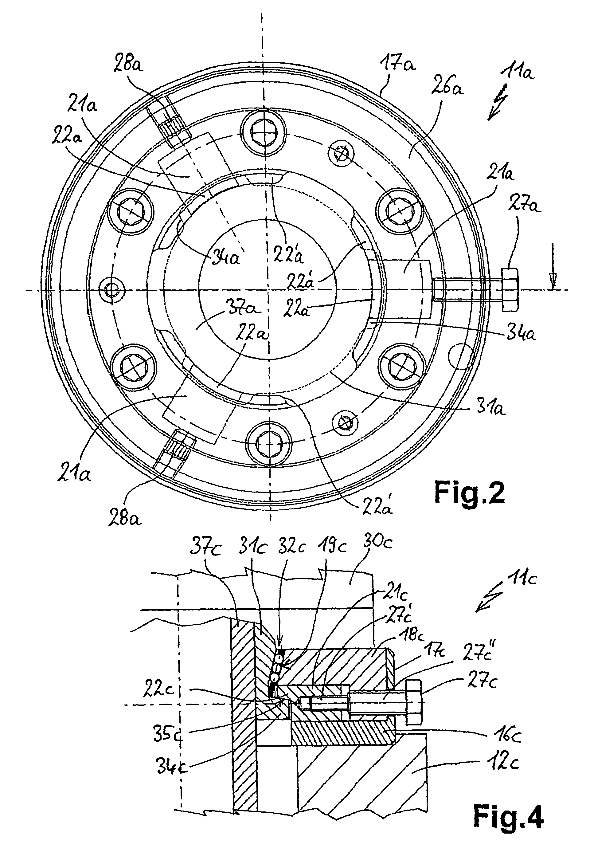
[0007]Thus, the advantage of a rapid, simple fixing by means of a bayonet lock can be used, which normally does not require tool use. Through the combination with locking by the locking means, it is also possible to ensure that the bayonet lock does not of its own accord become loosened or even released. Moreover as a result of locking, the connection between the clamping means and machine spindle can be given an even more accurate fit and more precise positioning. It is advantageously possible that on locking the bayonet lock the clamping means is drawn or pressed more strongly against or into the machine spindle. Locking should also take place very simply and in an easy to release manner. Advantageous developments of the invention are directed at this. The device also has a simple construction, so as to prevent maintenance work to the greatest possible extent. With the joining of the workpiece clamping system there can be a coupling to a machine power clamping device.
[0008]According to an embodiment of the invention, the bayonet lock has on the one hand projections on the clamping means and on the other projections on the machine spindle. These projections correspond to one another in such a way that they permit the function of a per se known bayonet lock. In the fixed state, i.e. when the bayonet lock is functioning, the projections are in engagement with one another by contact faces. These contact faces are inclined to the attachment direction, i.e. the direction in which the clamping means are moved up to or attached to the machine spindle. In the case of a rotating machine spindle said attachment direction is generally the rotation axis, so that the contact faces are also inclined to the machine spindle rotation axis. Advantageously at least one of the projections is movable in a direction inclined to the contact faces or inclined to the attachment direction. It is particularly advantageously movable perpendicular to the attachment direction, i.e. roughly precisely in the radial direction. Thus, through the movement of the projection the corresponding projection in the attachment direction is tightened, which permits the aforementioned intensification of fixing with increased retaining force or power.
[0009]The movable projection or the locking means of the bayonet lock are advantageously provided on the machine spindle. This offers the advantage that on the machine spindle it is possible to provide other devices, such as tension tubes or those which can bring about locking. This is frequently the case on machine spindles. It is also possible to fix to in each case one machine spindle different clamping means, particularly chucks, which have a simple construction and no movable parts or projections, without the clamping means requiring modifications with respect to the rigid projections in their part of the bayonet lock.
[0014]In an alternative development of the invention a bayonet lock is so constructed that only part of it, particularly the part constructed on the clamping means is rotatable or has to be rotated for fixing purposes. Both during fixing and on locking relative to the machine spindle, the clamping means does not have to be rotated or moved. This has the major advantage that with large, cumbersome clamping means there is no need for a movement and they can consequently be gripped and secured to the machine spindle. This e.g. permits the interlocking of continuous hydraulic lines, which are interconnected by corresponding connections between the machine spindle and clamping means. Moreover further functional passages are possible, if rotation is not necessary.
[0016]A projection can be moved by a force acting against a revolving force distributing element or a clamping ring, as described hereinbefore. It is also possible to provide a locking screw or the like, which moves the projection or part thereof for locking the bayonet lock. Alternatively to such a clamping ring, it is possible to provide on a force distributing element an inclined face with which it engages on the movable projection. The inclined face is inclined to the movement direction of the movable projection or its part. The angle between the inclined face and the attachment direction is preferably smaller than 90°, advantageously between 45° and 90°. The force distributing element can e.g. be moved in the attachment direction. Through the engagement of the inclined surface on the movable projection the latter is moved, said movement being in the form of a locking of the bayonet lock. As described for the clamping ring, it is advantageous if all the movable projections engage on the force distribution element. Thus, with a movement of the force distribution element it is possible to move all the projections or their parts.
[0017]Advantageously in this development of the invention the bayonet lock is provided in the outer area of the workpiece clamping system / machine spindle and clamping means or surrounds the same. A rotary retaining ring can be positioned externally or form part of the circumference of the clamping means or machine spindle. It is advantageously accessible at its outer circumferential surface, so that it can be easily gripped and rotated.