Performance enhancing contact module assemblies

a contact module and module technology, applied in the direction of coupling device connection, coupling device details, coupling device protection earth/shielding arrangement, etc., can solve the problems of backplane connectors having limits to high speed electrical performance, known connectors operating at the higher performance level of current systems

Active Publication Date: 2009-09-08
TYCO ELECTRONICS LOGISTICS AG (CH)
View PDF9 Cites 58 Cited by
  • Summary
  • Abstract
  • Description
  • Claims
  • Application Information

AI Technical Summary

Problems solved by technology

However, known connectors have problems operating at the higher performance levels of current systems.
For example, known backplane connectors have limits to high speed electrical performance in the areas such as crosstalk, noise persistence, footprint impedance, and skew.

Method used


Image

  • Performance enhancing contact module assemblies
  • Performance enhancing contact module assemblies
  • Performance enhancing contact module assemblies

Examples


Embodiment Construction

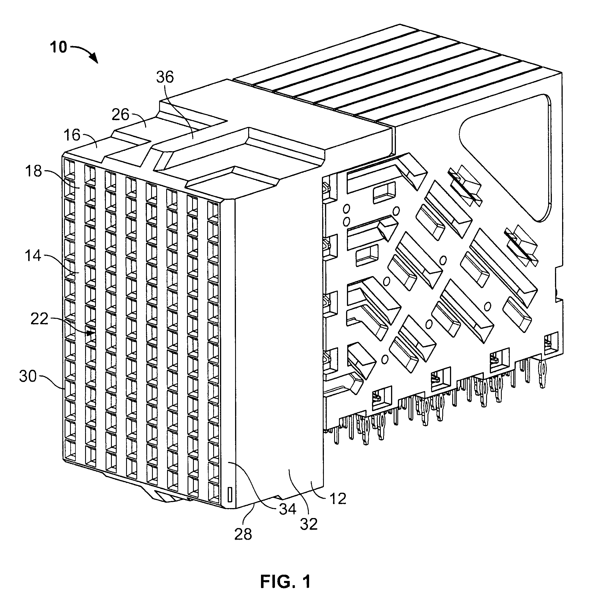
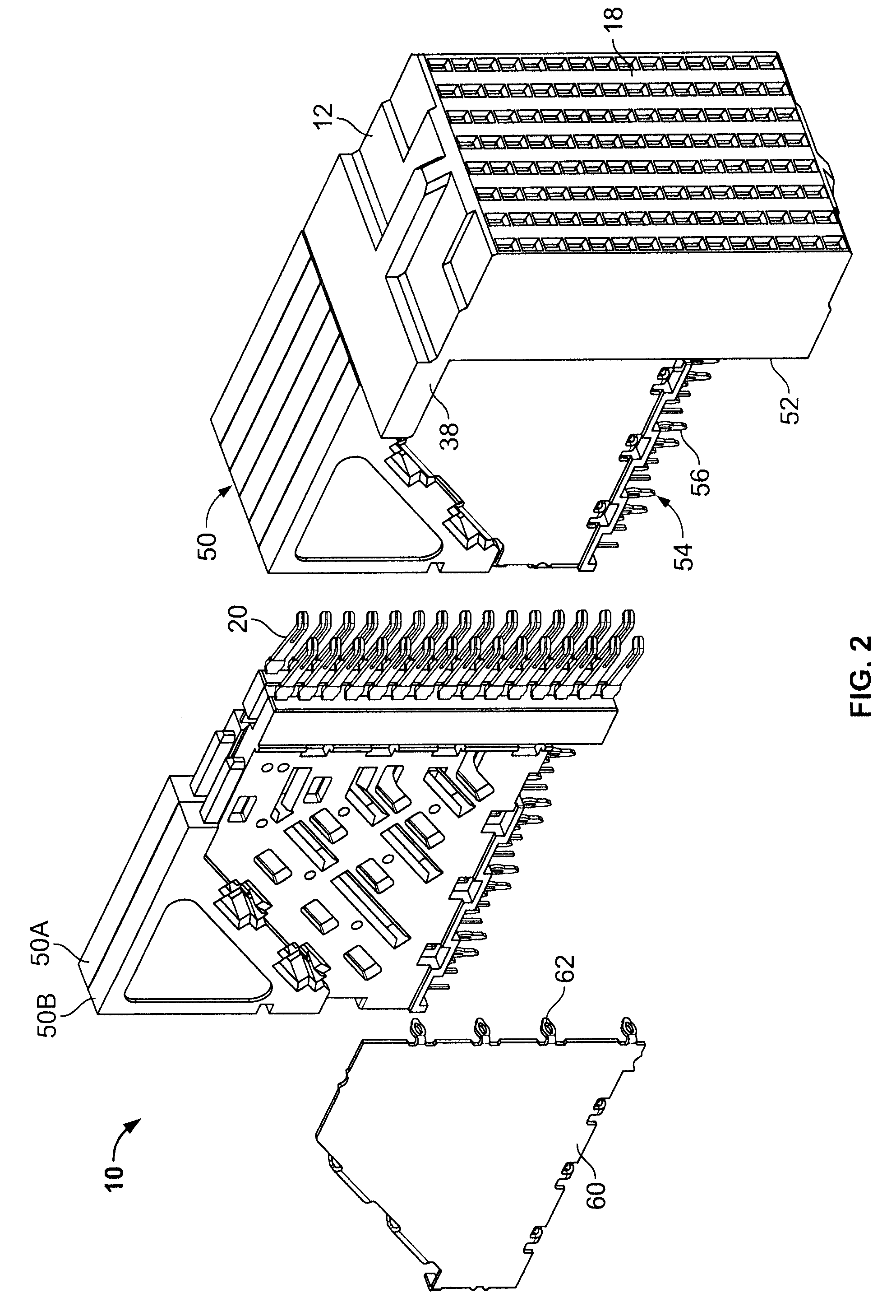
[0016]FIG. 1 illustrates an exemplary embodiment of an electrical connector 10. FIG. 2 is an exploded view of the electrical connector 10. While the connector 10 will be described with particular reference to a backplane receptacle connector, it is to be understood that the benefits herein described are also applicable to other connectors in alternative embodiments. The following description is therefore provided for purposes of illustration, rather than limitation, and is but one potential application of the subject matter herein.

[0017]As illustrated in FIG. 1, the connector 10 includes a dielectric housing 12 having a forward mating end 14 that includes a shroud 16 and a mating face 18. The mating face 18 includes a plurality of mating contacts 20 (shown in FIG. 2), such as, for example, contacts within contact cavities 22, that are configured to receive corresponding mating contacts (not shown) from a mating connector (not shown). The shroud 16 includes an upper surface 26 and a ...


PUM


Abstract

A contact module assembly includes a dielectric body having a mating end with a plurality of mating contacts and a mounting end with a plurality of mounting contacts. A lead frame is at least partially encased by the dielectric body, wherein the lead frame has a plurality of conductors representing both signal conductors and ground conductors extending alone a lead frame plane. The signal and ground conductors extend from respective ones of the mating contacts and the mounting contacts, wherein at least some of the ground conductors include a mating contact terminal proximate the respective mating contact and a mounting contact terminal proximate the respective mounting contact. The ground conductors extend only partially between the mating contact and the mounting contact associated with the respective ground conductor such that a gap exists between the mating contact terminal and the mounting contact terminal of the ground conductor. A commoning member electrically connects the mating contact terminal and the mounting contact terminal of at least one of the ground conductors, wherein the commoning member is oriented in a non-coplanar relation with the lead frame plane.

Description

BACKGROUND OF THE INVENTION[0001]The subject matter herein relates generally to electrical connectors, and more particularly, to back plane connectors.[0002]With the ongoing trend toward smaller, faster, and higher performance electrical components such as processors used in computers, routers, switches, etc., it has become increasingly important for the electrical interfaces along the electrical paths to also operate at higher frequencies and at higher densities with increased throughput. For example, performance demands for video, voice and data drive input and output speeds of connectors within such systems to increasingly faster levels.[0003]In a traditional approach for interconnecting circuit boards, one circuit board serves as a back plane and the other as a daughter board. The back plane typically has a connector, commonly referred to as a header, which includes a plurality of signal contacts which connect to conductive traces on the back plane. The daughter board connector,...

Claims


Application Information

Patent Timeline
Patent Type & Authority Patents(United States)
IPC IPC(8): H01R13/648H01R12/71
CPCH01R13/514H01R13/65807H01R13/6587H01R12/725H01R23/688H01R13/6471H01R13/6586
Inventor MCALONIS, MATTHEW RICHARDSIPE, LYNN ROBERTFEDDER, JAMES LEEROTHERMEL, BRENT RYANGLOVER, DOUG W.
Owner TYCO ELECTRONICS LOGISTICS AG (CH)
Why Eureka
Try Eureka