Baseball or softball bat

a softball bat and base ball technology, applied in the field of softball bats, can solve the problems of unsatisfactory hitting feeling and not much improved restitution characteristic at the hitting portion of the bat, and achieve the effect of preventing degraded hitting feeling and improving restitution characteristi

Inactive Publication Date: 2009-09-08
MIZUNO CORPORATION
View PDF21 Cites 29 Cited by
  • Summary
  • Abstract
  • Description
  • Claims
  • Application Information

AI Technical Summary

Benefits of technology

[0010]The present invention was made to solve the above-described problem and its object is to provide a baseball or softball bat having improved restitution characteristic and capable of preventing degraded feel of hitting caused by vibration or shock at the time of hitting.

Problems solved by technology

The conventionally proposed bats described above, however, have the following problems.
Specifically, in the bat disclosed in Patent Document 1, though different materials are laminated at the hitting portion of the bat, these layers are adhered and integrated to each other, and therefore, restitution characteristic is not much improved at the hitting portion of the bat at the time of hitting the ball.
Further, dependent on the adhesion strength between the tubular insert and the inner wall of the hitting portion, the tubular insert may possibly be separated from the inner wall at the hitting portion, due to repeated hitting during use.
As a result, such vibration and shock can be alleviated only moderately, and hence, feeling of hitting with the bat could be unsatisfactory.

Method used


Image

  • Baseball or softball bat
  • Baseball or softball bat
  • Baseball or softball bat

Examples


embodiment 1

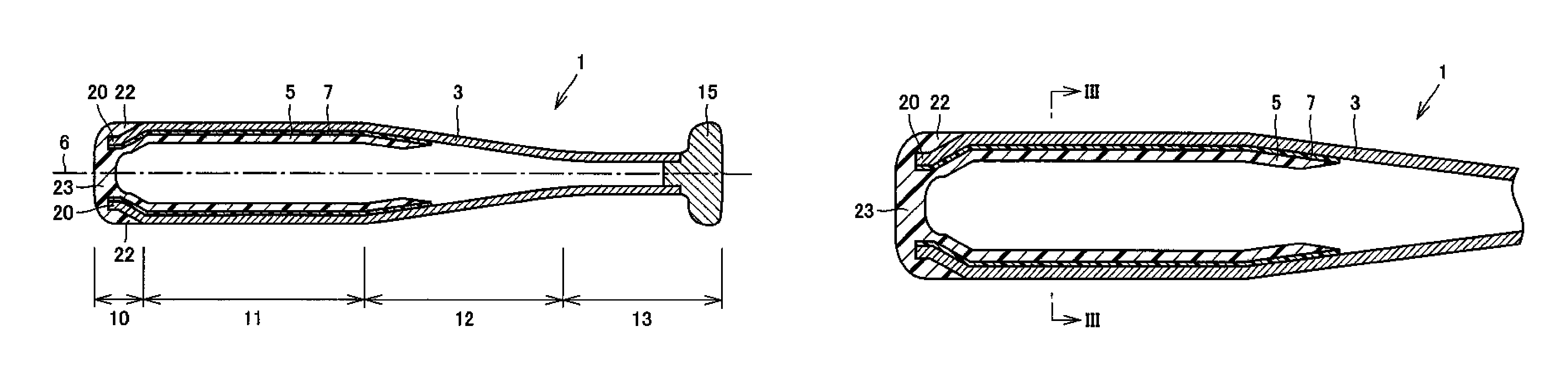
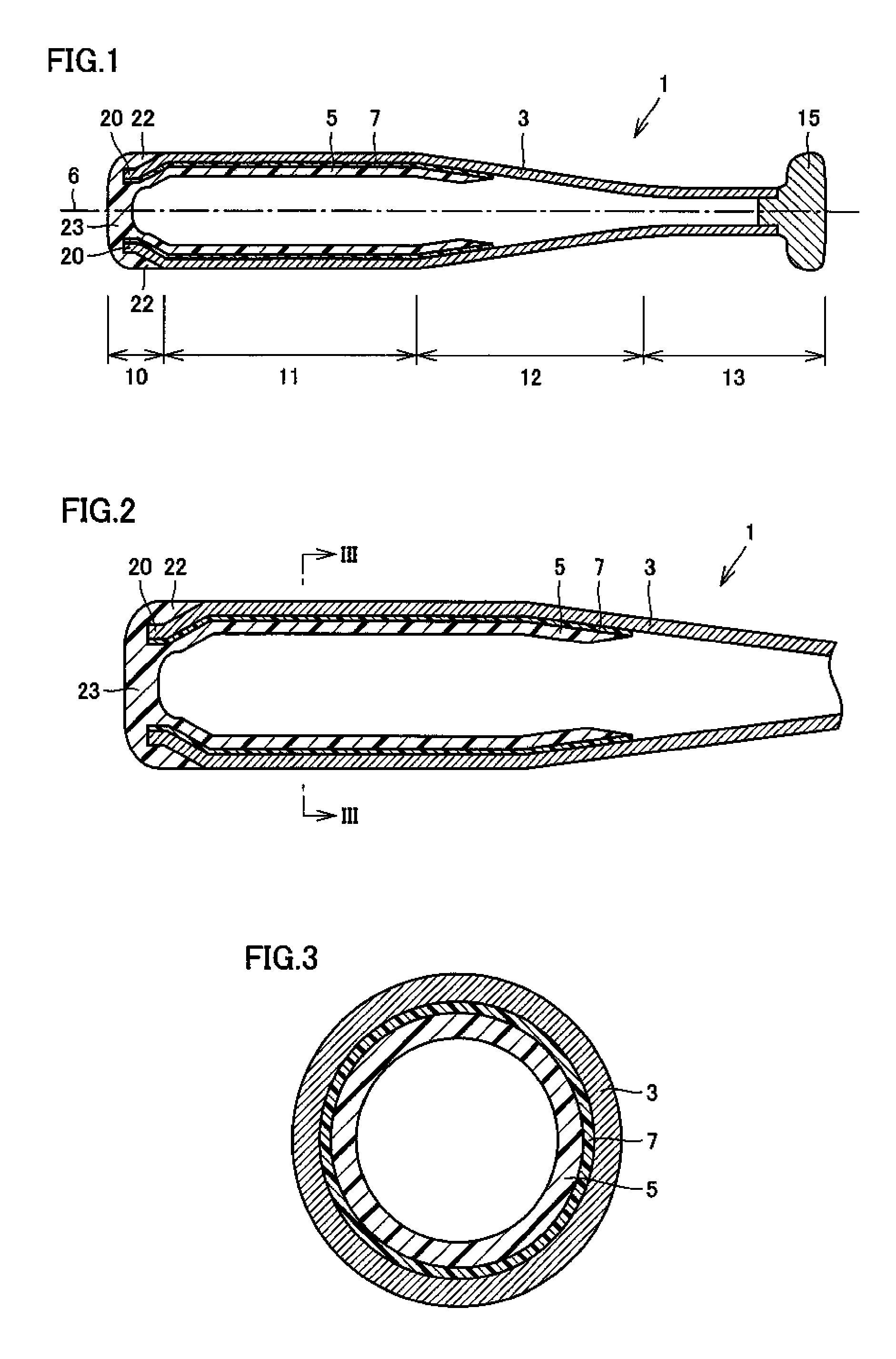
[0047]Referring to FIGS. 1 to 3, Embodiment 1 of the bat in accordance with the present invention will be described.

[0048]Referring to FIGS. 1 to 3, a bat 1 in accordance with the present invention includes, from the tip end side, a tip end 10, a hitting portion 11, a tapered portion 12 and a grip portion 13. Bat 1 includes an outer circumferential member 3 extending from tip end 10 to grip portion 13 and defining the shape of the bat as a whole; an inner circumferential member 5 adhered to outer circumferential member 3 on the side of tip end 10 of outer circumferential member 3; a grip end 15 connected and fixed to outer circumferential member 3 at the end of grip portion 13 (rear end of bat 1); and a non-adhesive portion 7 as a weak boundary layer (WBL) arranged between outer circumferential member 3 and inner circumferential member 5 positioned on the side of inner circumferential surface at hitting portion 1 of outer circumferential member 3. At hitting portion 11, as shown in ...

embodiment 2

[0073]Referring to FIGS. 6 and 7, Embodiment 2 of the bat in accordance with the present invention will be described. FIGS. 6 and 7 correspond to FIGS. 2 and 3, respectively.

[0074]Bat 1 shown in FIGS. 6 and 7 basically has the same structure as the bat shown in FIGS. 1 to 3, with the structure of inner circumferential member 5 made different. Specifically, in bat 1 shown in FIGS. 6 and 7, inner circumferential member 5 consists of concentric inner circumferential member parts 5a, 5b and a non-adhesive portion 7b. Non-adhesive member 7b is positioned between inner circumferential member parts 5a and 5b. Non-adhesive portion 7b is arranged to extend from the taper side end portion 5 of inner circumferential member part 5b to the tip end 23 of the inner circumferential member. As a result, inner circumferential member parts 5a and 5b are movable independent from each other at the side of tapered portion 12, while they are connected on the side of tip end 23 of the inner circumferential...

embodiment 3

[0082]Embodiment 3 of the bat in accordance with the present invention will be described with reference to FIG. 9. FIG. 9 corresponds to FIG. 2.

[0083]Referring to FIG. 9, bat 1 of the present invention basically has the same structure as the bat shown in FIGS. 1 to 3, with the structure of tip end portion of the bat made different. Specifically, in the bat shown in FIG. 9, as a member forming the tip end portion of bat 1, a cap member 27 is arranged to cover the end portion of outer circumferential member 3, separate from inner circumferential member 5. Cap member 27 is adhered to the outer surface of outer circumferential member 3 at tip end portion 10 (see FIG. 1) of the bat. Further, tip end 23 of inner circumferential member is arranged to fill the opening at the tip end 20 of outer circumferential member. The surface of tip end 20 of outer circumferential member as the inner circumferential surface of the opening and the outer circumferential surface of tip end 23 of inner circ...


PUM


Abstract

A baseball or softball bat having improved restitution characteristic and preventing degraded hitting feeling caused by vibration or impact at the time of hitting can be provided. The baseball or softball bat including a ball hitting portion, a tapered portion and a grip portion is provided with an outer circumferential member, an inner circumferential member and a non-adhesive portion. The outer circumferential member is a cylindrical member forming at least the ball hitting portion. The inner circumferential member is arranged on the inner circumferential side of the outer circumferential member. The inner circumferential member has a tip end of the inner circumferential member positioned opposite to a taper side end as an end portion on the side of the tapered portion, fixed to the outer circumferential member. The non-adhesive portion is arranged, for preventing adhesion between the outer circumferential member and an unfixed portion of the inner circumferential member other than the tip end portion of the inner circumferential member and including the taper side end, at least on a portion of a region where the unfixed portion of the inner circumferential member and the outer circumferential member are opposite to each other.

Description

[0001]This nonprovisional application is based on Japanese Patent Applications Nos. 2006-295920 and 2007-264003 filed with the Japan Patent Office on Oct. 31, 2006 and Oct. 10, 2007, respectively, the entire contents of which are hereby incorporated by reference.BACKGROUND OF THE INVENTION[0002]1. Field of the Invention[0003]The present invention relates to a baseball or softball bat and, more specifically, to a baseball or softball bat having superior restitution characteristic.[0004]2. Description of the Background Art[0005]Baseball or softball bats formed of various materials including wood, metal such as titanium, titanium alloy and aluminum alloy, and fiber-reinforced plastic prepared by impregnating carbon fiber, glass fiber or the like with matrix resin and curing, have been available in the market.[0006]Conventionally, in order to improve restitution characteristic of a bat, Japanese Patent Laying-Open No. 2002-052108 (Patent Document 1) discloses a bat having a tubular inse...

Claims


Application Information

Patent Timeline
Patent Type & Authority Patents(United States)
IPC IPC(8): A63B59/06A63B59/51A63B59/56A63B102/18
CPCA63B59/06A63B2102/18A63B59/50A63B59/56A63B2102/182
Inventor MISONO, KAZUNORIYAMAGUCHI, YUTAKAKIDA, TOSHIAKI
Owner MIZUNO CORPORATION
Why Eureka
Try Eureka