
Direct current breaker through combination of magnetic induction transfer and current-limiting protection

A technology of DC circuit breaker and current limiting protection, applied in the direction of emergency protection circuit device for limiting overcurrent/overvoltage, emergency protection circuit device, automatic disconnection emergency protection device, etc., can solve the complex water cooling system, cost Expensive and other problems, to achieve the effects of good recovery characteristics, short arcing time, and reduced voltage level and volume

Inactive Publication Date: 2017-04-05
XI AN JIAOTONG UNIV
View PDF6 Cites 3 Cited by
  • Summary
  • Abstract
  • Description
  • Claims
  • Application Information

AI Technical Summary

Problems solved by technology

When a short-circuit fault occurs in the power system, the rapidly rising short-circuit current will cause very serious consequences
[0003] Typical hybrid circuit breakers use fully-controlled power electronic devices to achieve rapid transfer and breaking of current, which is expensive and requires a complex water cooling system, which is difficult to promote in future medium and high voltage DC systems

Method used


Image

  • Direct current breaker through combination of magnetic induction transfer and current-limiting protection
  • Direct current breaker through combination of magnetic induction transfer and current-limiting protection
  • Direct current breaker through combination of magnetic induction transfer and current-limiting protection

Examples


Embodiment Construction

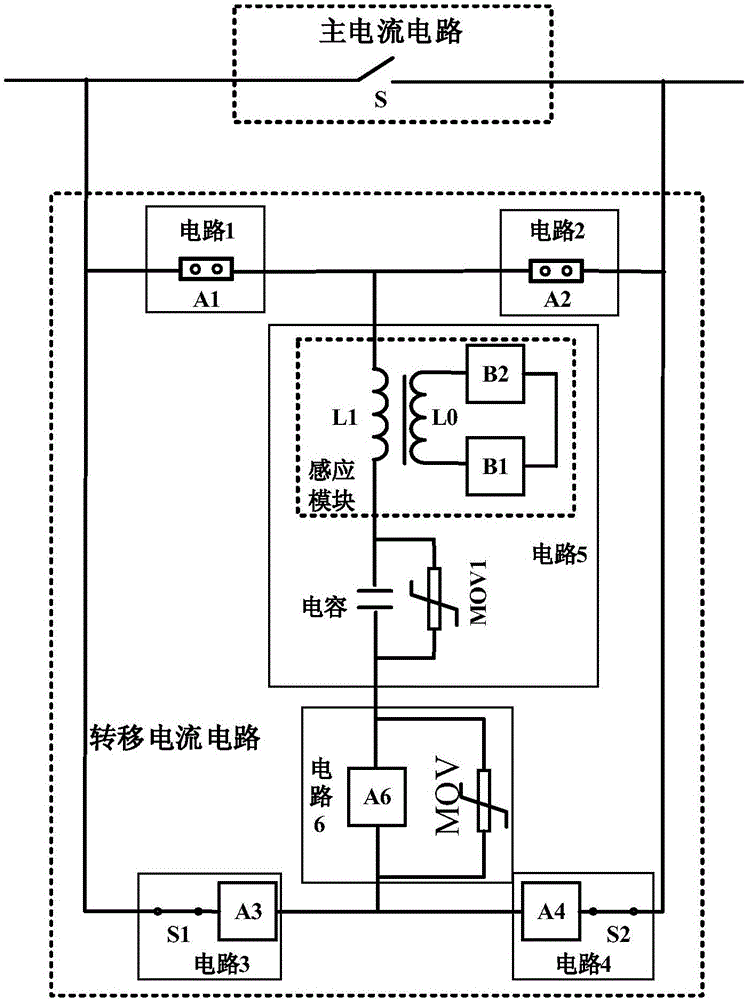
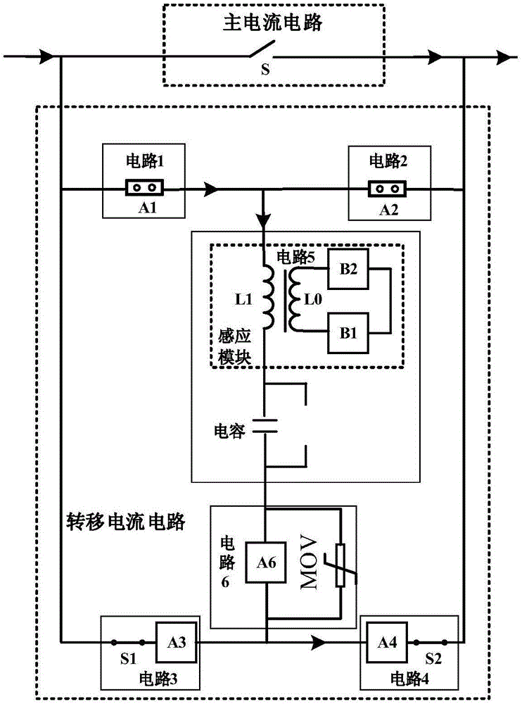
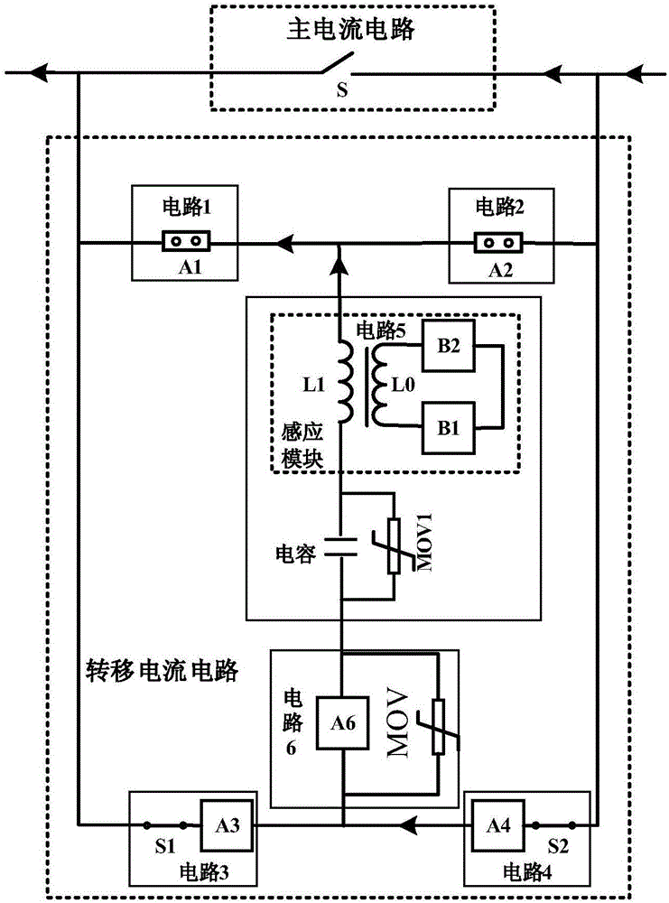
[0040] The following is attached Figure 1-9 A specific embodiment of the present invention will be described.

[0041] In one embodiment, the present invention discloses a DC circuit breaker combining magnetic induction transfer and current limiting protection. The circuit breaker includes a main current circuit and a transfer current circuit;

[0042] The main current circuit is used to pass current under normal working conditions;

[0043] The transfer current circuit is used to transfer the short-circuit fault current from the main current circuit when the short-circuit fault current occurs.

[0044] In this example, if figure 1 The schematic diagram of the structure of the circuit breaker body shown includes the main current circuit, the transfer current circuit and the overvoltage limiting circuit. In order to better illustrate the breaking process of the circuit breaker, such as figure 2 The schematic diagram of the structure of the circuit breaker current from lef...


PUM


Abstract

A direct current breaker through combination of magnetic induction transfer and current-limiting protection comprises a main current circuit and a transfer current circuit. The main current circuit is connected in parallel with the transfer current circuit; the main current circuit is a rapid switch; the transfer current circuit consists of a circuit 1, a circuit 2, a circuit 3, a circuit 4, a circuit 5 and a circuit 6 which form a bridge circuit; the circuit 1 is connected in series with the circuit 2 and is connected in parallel with the main current circuit; and the circuit 1 and the circuit 2 can be vacuum and gas trigger gaps or high-speed mechanical switches or the combination thereof, the transfer current circuit employs the bridge structure and only uses one set of single-direction assembly having the breaking function to realize the dual-direction disconnection of the current, and the usage amount reduces 50% compared to the usage amount of the current structure turn-off device. The transfer circuit is internally provided an auxiliary energy dissipation module circuit 5 and a breaking module circuit 6, the current of the main circuit is transferred to the auxiliary energy dissipation module to further reduce the usage amount of the turn-off assembly in the breaking module, and the total usage amount of the turn-off device can be changed to the 1 / 4 of the current usage amount, and the cost of the breaker is reduced.

Description

technical field [0001] The invention belongs to the field of medium and high voltage circuit breakers, in particular to a DC circuit breaker combining magnetic induction transfer and current limiting protection. Background technique [0002] With the continuous improvement of power system capacity, DC power transmission and transformation equipment is booming, and at the same time, higher requirements are placed on system stability and safety. Among the various faults that may occur in the power system, short-circuit faults are the most harmful to the power grid and have a high probability of occurrence. When a short-circuit fault occurs in the power system, the rapidly rising short-circuit current will cause very serious consequences. [0003] Typical hybrid circuit breakers use fully-controlled power electronic devices to achieve rapid transfer and breaking of current, which is expensive and requires a complex water cooling system, which is difficult to promote in future ...

Claims


Application Information

Patent Timeline
Patent Type & Authority Applications(China)
IPC IPC(8): H02H3/087H02H9/02H02H9/04
CPCH02H3/087H02H9/021H02H9/047Y02E40/60
Inventor 杨飞荣命哲吴益飞吴翊纽春萍胡杨
Owner XI AN JIAOTONG UNIV
Learn More