Disk drive with servo synchronous recording

a technology of synchronous recording and disk drive, applied in the field of disk drives, can solve the problems of reducing the capacity of the disk drive, no means are provided for adjusting the read/write data frequency with respect to the clock mark read-back pulse frequency, and avoiding data read errors

Inactive Publication Date: 2005-03-29
HITACHI GLOBAL STORAGE TECH NETHERLANDS BV
View PDF7 Cites 15 Cited by
  • Summary
  • Abstract
  • Description
  • Claims
  • Application Information

AI Technical Summary

Benefits of technology

The present invention provides a system and a method for synchronizing write and read clocks to a predefined servo information bit spacing, thereby avoiding data read errors that are caused when the data preamble is corrupted. Specifically, the present invention synchronizes both the write and read clocks to the written servo information bit spacing within a servo sector of a disk so that written data transitions are correlated with the servo information bit spacing.

Problems solved by technology

Moreover, synchronization fields add to the data format overhead, thereby reducing disk drive capacity.
In that system, no means are provided for altering the read / write data frequency with respect to the clock mark read-back pulse frequency, or for data recovery in the presence of errors in the clock marks.

Method used


Image

  • Disk drive with servo synchronous recording
  • Disk drive with servo synchronous recording
  • Disk drive with servo synchronous recording

Examples


example 1

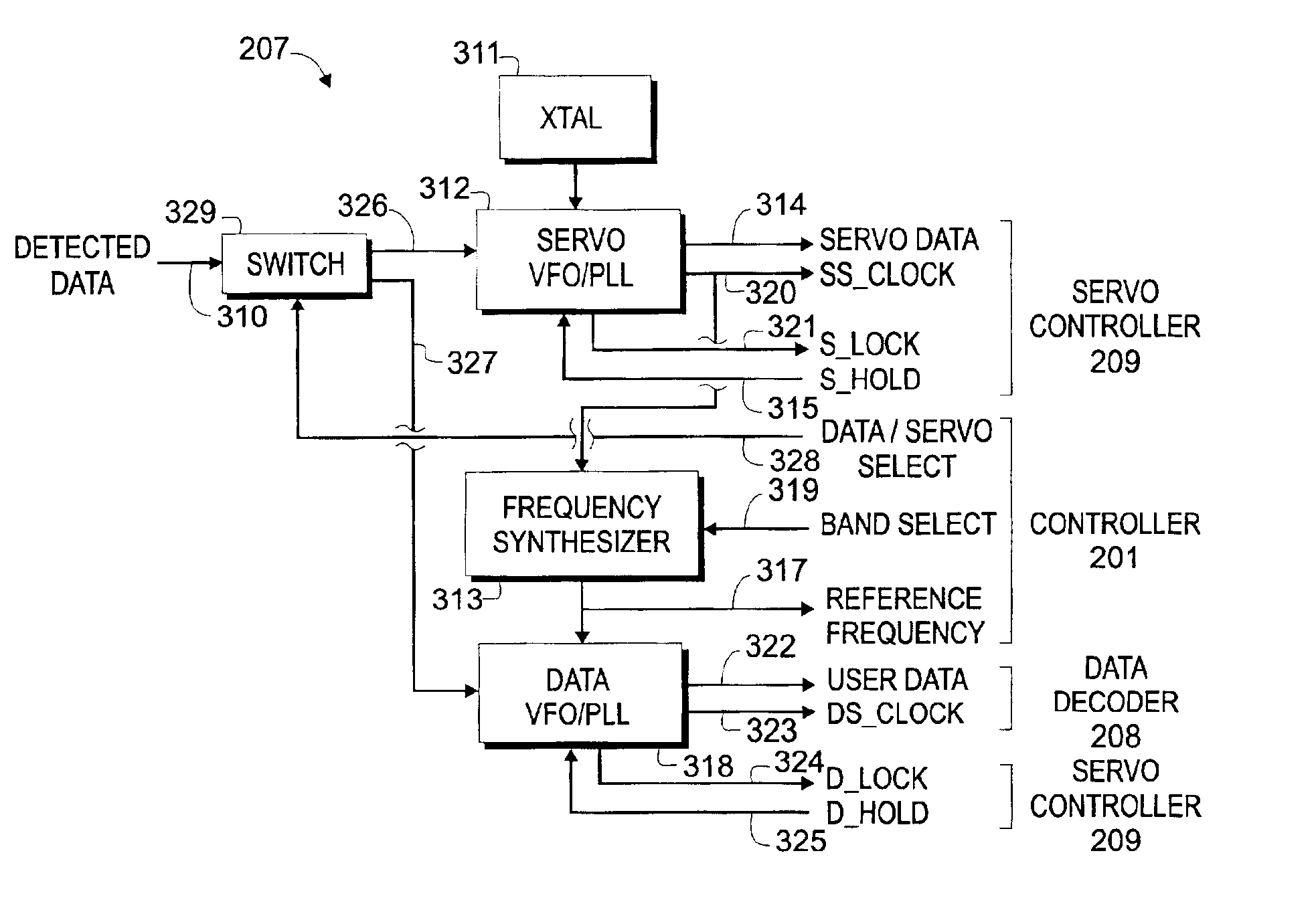
Data band 1 is requested, and the input 320 to the frequency synthesizer 313 is 40 MHz. For this example, information on band select 319 would instruct synthesizer 313 to multiply clock 320 by a factor of 1.1, resulting in an output reference frequency 317 of 44 MHz.

example 2

Data band 2 is requested, and the input 320 to frequency synthesizer 313 is 40 MHz. For this example, information on band select 319 would instruct synthesizer 313 to multiply clock 320 by a factor of 1.15, resulting in an output reference frequency 317 of 46 MHz.

During a data write operation, controller 201 uses reference frequency 317 to clock un-encoded data to data encoder 202. Thus, the data is written synchronous with the servo information 326. During a data read operation, controller 201 sends detected data 310 to input 327 of data VFO / PLL 318 using switch 329. Controller 201 then operates data VFO / PLL 318 in the conventional well-known manner. The exception being that the reference frequency 317 input to the data VFO / PLL is synchronous with the servo information, instead of a fixed frequency input.

FIG. 5 shows the in-track spacing T1, T2, T3, T4, and the radial or cross-track spacing relationship of servo information bits 406, 407, 408, 409 within servo sector 401, that span...


PUM

PropertyMeasurementUnit
frequencyaaaaaaaaaa
frequencyaaaaaaaaaa
frequencyaaaaaaaaaa

Abstract

A read clock circuit for a disk drive includes a phase-locked loop/voltage controlled oscillator (VFO/PLL) and a frequency synthesizer. The VFO/PLL receives a servo sector transition signal that is related to detected transitions in a servo sector field of a magnetic recording disk, and outputs a servo frequency signal that is synchronous to the servo sector transition signal. The frequency synthesizer receives the servo frequency signal and generates the read clock signal that is synchronous with the servo frequency signal. In a banded recording disk drive the frequency synthesizer generates a unique read clock signal for each data band.

Description

FIELD OF THE INVENTIONThis invention relates to disk drives, and more particularly to a system and method for generating read and write clock signals for a magnetic recording disk drive that results in improved format efficiency, performance, and tolerance to read errors.BACKGROUND OF THE INVENTIONFIG. 1 is a functional block diagram of a conventional disk drive 100 having a crystal oscillator circuit 108 that provides an asynchronous write clock. Disk drive 100 includes a disk 101, a spindle motor 102 for rotating the disk, a spindle controller 103, a head 104 for reading or writing, an actuator 105 for moving the head across the disk, read / write and servo processing circuit 106, a data channel 107, and an oscillator circuit 108. Disk drive 100 is typically a banded recording or zoned bit recording (ZBR) disk drive with a sector servo architecture, as shown by disk 101 with annular data bands 109 and equally angularly spaced servo sectors, such as typical servo sectors 111, extendi...

Claims


Application Information

Patent Timeline
Patent Type & Authority Patents(United States)
IPC IPC(8): G11B20/14G11B27/30G11B5/09
CPCG11B5/09G11B27/3027G11B20/1403G11B2220/20
Inventor HETZLER, STEVEN R.KABELAC, WILLIAM JOHN
Owner HITACHI GLOBAL STORAGE TECH NETHERLANDS BV
Why Eureka
Try Eureka