Tool

a tool and tool body technology, applied in the field of tools, can solve the problems of forming a complicated structure and a lot of components of the tool, and achieve the effects of simple structure, easy operation of the tool, and small number of elements

Inactive Publication Date: 2009-09-15
LIOU MOU TANG
View PDF12 Cites 17 Cited by
  • Summary
  • Abstract
  • Description
  • Claims
  • Application Information

AI Technical Summary

Benefits of technology

[0007]An advantage of the tool according to the present invention is its small number of elements and simple structure.
[0008]Another advantage of the tool according to the present invention is that a user can easily operate the tool with only one hand.

Problems solved by technology

The tool includes a lot of components and forms a complicated structure.

Method used


Image

  • Tool
  • Tool
  • Tool

Examples


Embodiment Construction

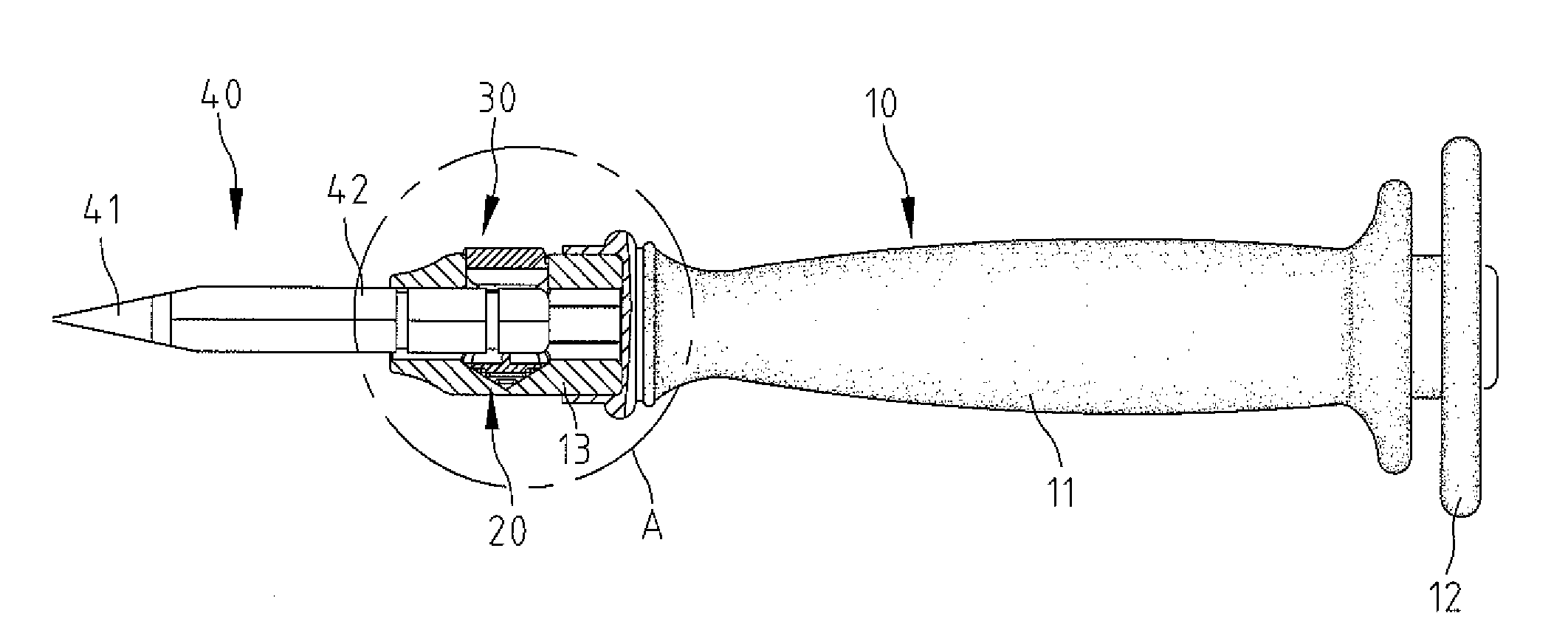
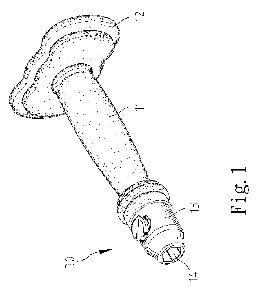
[0023]Referring to FIG. 1, there is shown a tool 10 according to a first embodiment of the present invention. The tool 10 includes a handle 11, an anvil 12 formed at an end of the handle 11 and a socket 13 formed at an opposite end of the handle 11. The anvil 12 is for encountering a hammer. The anvil 12 includes a large area for protecting a user's hand from the hammer. A controller 30 is installed on the socket 13.

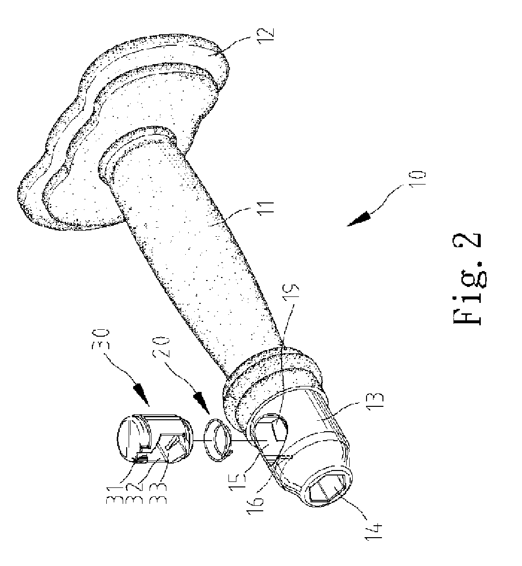
[0024]Referring to FIGS. 2 and 3, the socket 13 defines a first axial non-circular space 14, a second axial non-circular space 19, a radial space 15 for communicating the first axial non-circular space 14 with the second axial non-circular space 19 and a radial taper cavity 17 in communication with the radial space 15. Preferably, the axial non-circular spaces 14 and 19 are hexangular spaces. The radial taper cavity 17 is made by a tip of a drill. In another embodiment, a radial flat-bedded cavity may be made instead of the radial taper cavity 17 if milling is adopted in...


PUM


Abstract

A tool includes a handle, a controller and a bit. The handle includes a socket defining an axial non-circular space and a radial space in communication with the axial space. The controller includes a space defined therein and a ridge formed on the wall of the space thereof. The controller is movable in the radial space of socket between a locking position and a releasing position. The bit includes a working tip and a shank defining at least one recess for receiving the ridge when the shank is inserted into the space of the controller through the axial space of the socket, thus locking the bit to the handle.

Description

BACKGROUND OF INVENTION[0001]1. Field of Invention[0002]The present invention relates to a tool and, more particularly, to a tool including a chuck for engagement with a bit.[0003]2. Related Prior Art[0004]Disclosed in Taiwanese Patent Publication No.554796 is a tool including a chuck 20 for engagement with a bit 40. The chuck 20 includes a socket 21, a ball 24 and two rings 26 and 28. The rings 26 and 28 can be rotated on the socket 21 so as to move the ball 24 longitudinally and peripherally on the socket 21 so that the bit 40 can be engaged with and disengaged from the chuck 20. The tool includes a lot of components and forms a complicated structure. Moreover, a user has to operate the chuck 20 with two hands.[0005]The present invention is therefore intended to obviate or at least alleviate the problems encountered in the prior art.SUMMARY OF INVENTION[0006]According to the present invention, a tool includes a handle, a controller and a bit. The handle includes a socket defining ...

Claims


Application Information

Patent Timeline
Patent Type & Authority Patents(United States)
IPC IPC(8): B25G1/10
CPCB25B23/0035B25D1/14B25D3/00B25G3/18Y10T16/498Y10T16/469B25D2250/111
Inventor LIOU, MOU-TANG
Owner LIOU MOU TANG
Why Eureka
Try Eureka