Cordless fastener tool with fastener driving and rotating functions

a technology of fastener and driving function, which is applied in the direction of manufacturing tools, percussive tools, portable drilling machines, etc., can solve the problems of difficulty in penetration of frame members, structural weakened boards, and need additional finishing, so as to reduce the installation time of wallboards and increase the driving force

Inactive Publication Date: 2009-09-15
ILLINOIS TOOL WORKS INC
View PDF22 Cites 21 Cited by
  • Summary
  • Abstract
  • Description
  • Claims
  • Application Information

AI Technical Summary

Benefits of technology

[0012]The above-listed needs are met or exceeded by the present fastener-driving tool which overcomes the limitations of the current technology. In the present tool, pneumatic power is replaced by a combustion power source, eliminating the need for a separate compressor and pressure hose. Thus, the present tool is completely portable. The present tool is provided with a combustion engine for driving the fastener into the workpiece, and an electric motor for rotating the driver blade and the engaged fastener. In addition, the combustion power source provides greater driving force than the prior art pneumatic tool. Also, the present tool controls the combustion-generated driver blade recoil so that the driver blade maintains engagement with the fastener during the rotation phase of the installation process. When used with cutting tip threaded fasteners, wallboard installation time is reduced, and wallboard is more securely attached to the frame members.

Problems solved by technology

While these tools have been widely accepted for use in rough framing as well as finish construction, users have been forced to use other tools for installing wallboard to frame members such as metal or wooden studs.
If the fastener passes through the face paper, the board is structurally weakened at that point, and may require additional finishing.
Another installation factor of wallboard installation is that when wallboard is applied to metal frame members, the fastener typically easily passes through the wallboard, but in some cases has difficulty penetrating the frame member.
Subsequent tightening of the fastener by the power applicator tool fails to form a tight connection between the wallboard and the frame member at that point.
One drawback of this tool is that, being pneumatically powered; it requires a remote compressor connected to the tool with a pressure hose.
Such hoses are bulky and awkward to work around in many workplaces.
Compressors are noisy and cannot always be used indoors.
Another drawback of the disclosed tool is that it has insufficient power to drive fasteners into metal frame members.
Still another drawback of the disclosed tool is that as the driver blade forces the fastener against the metal frame member, the pneumatic impact force generates recoil which causes a fastener-driving bit at the end of the driver blade to become disengaged from the fastener head.

Method used


Image

  • Cordless fastener tool with fastener driving and rotating functions
  • Cordless fastener tool with fastener driving and rotating functions
  • Cordless fastener tool with fastener driving and rotating functions

Examples


Embodiment Construction

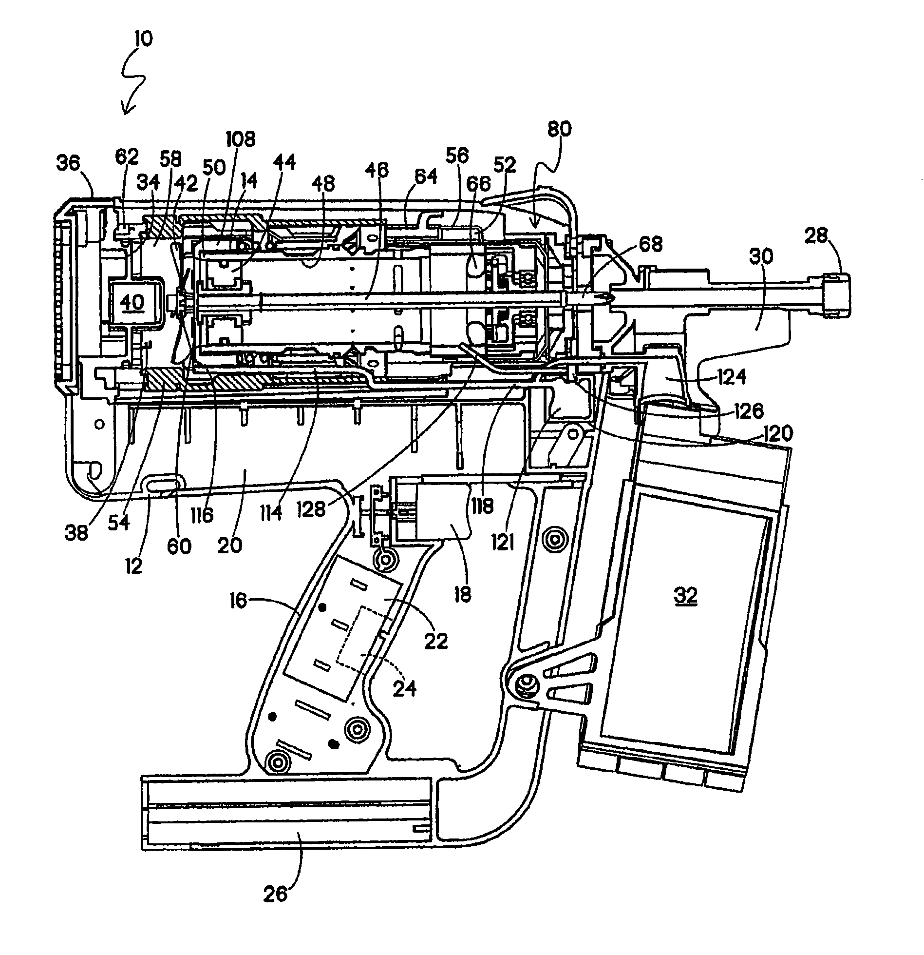
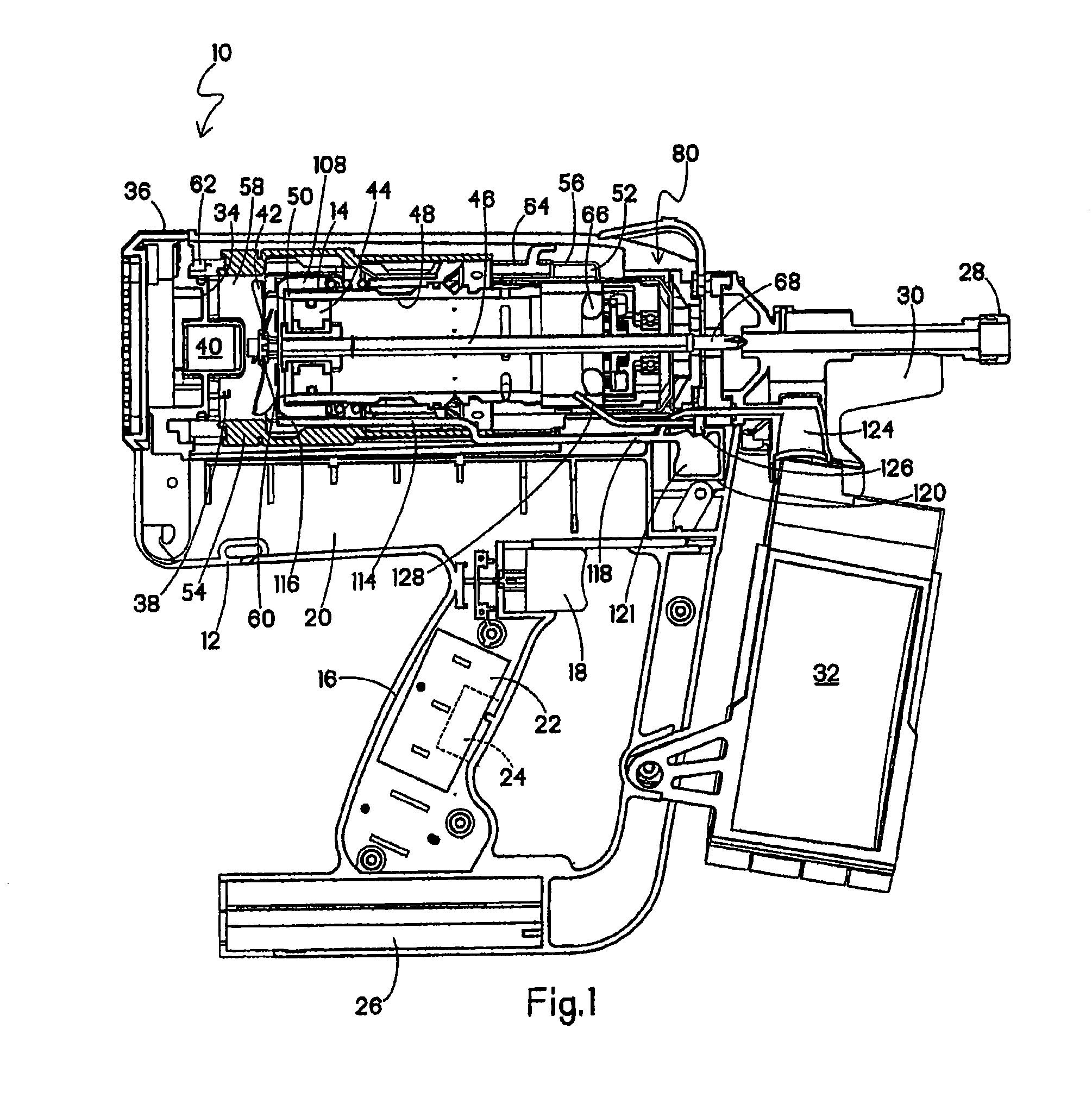
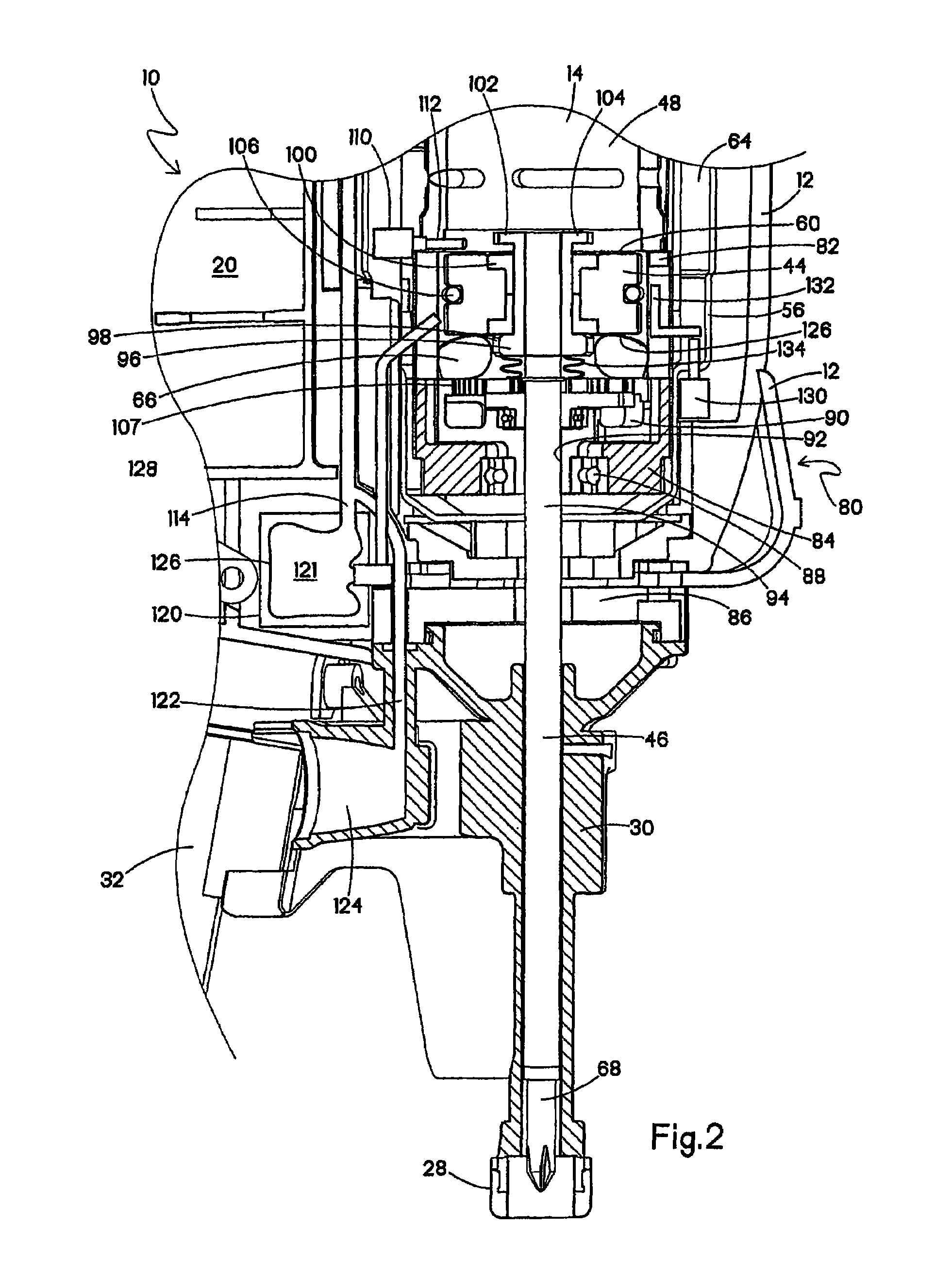
[0020]Referring now to FIGS. 1 and 2, a fastener-driving tool or combustion nailer incorporating the present invention is generally designated 10 and preferably is of the general type described in detail in the patents listed above and incorporated by reference in the present application. A housing 12 of the tool 10 encloses a self-contained internal combustion power source 14 as is known in the art. Included on the housing 12 is a handle 16 with a trigger 18. A fuel cell chamber 20 encloses a fuel cell (not shown) which provides pressurized fuel for combustion.

[0021]Preferably located within the handle 16, but potentially located elsewhere within the housing 12 is a control system 22 including a central processing unit CPU having a control program 24 (shown hidden). As is known in the art, the control program 24 controls the operation of the tool 10, including fuel delivery if electronic fuel injection is provided, fan rotation when a fan is located within the combustion chamber, a...


PUM

PropertyMeasurementUnit
electrical poweraaaaaaaaaa
return forceaaaaaaaaaa
volumeaaaaaaaaaa

Abstract

A fastener-driving tool includes a combustion power source configured for driving a driver blade linearly towards a workpiece, and an electrical power source associated with the combustion power source for rotationally driving the driver blade upon completion of the linear travel, both power sources being disposed in the tool.

Description

RELATED APPLICATION[0001]The present application claims priority under 35 USC § 119(e) from U.S. Ser. No. 60 / 877,983 filed Dec. 29, 2006.BACKGROUND[0002]The present invention relates generally to fastener-driving tools used to drive fasteners into workpieces, and specifically to combustion-powered fastener-driving tools, also referred to as combustion tools or combustion nailers.[0003]Combustion-powered tools are known in the art. Representative tools are manufactured by Illinois Tool Works, Inc. of Glenview, Ill. for use in driving fasteners into workpieces, and are described in commonly assigned patents to Nikolich U.S. Pat. Re. No. 32,452, and U.S. Pat. Nos. 4,522,162; 4,483,473; 4,483,474; 4,403,722; 5,133,329; 5,197,646; 5,263,439 and 6,145,724 all of which are incorporated by reference herein.[0004]Such tools incorporate a tool housing enclosing a small internal combustion engine or power source. The engine is powered by a canister of pressurized fuel gas, also called a fuel c...

Claims


Application Information

Patent Timeline
Patent Type & Authority Patents(United States)
IPC IPC(8): B25B21/02
CPCB25B21/023B25C1/08B25C1/00B25B27/0085
Inventor PANASIK, CHERYL L.
Owner ILLINOIS TOOL WORKS INC
Why Eureka
Try Eureka