InGaAs/GaAs lasers on silicon produced by LEPECVD and MOCVD

a technology of gaas lasers and silicon, which is applied in the direction of laser details, nanooptics, semiconductor devices, etc., can solve the problems of reducing the performance of gaas lasers, reducing the surface roughness of gaas lasers, and reducing the speed of gaas lasers

Inactive Publication Date: 2009-09-15
DICHROIC CELL
View PDF12 Cites 10 Cited by
  • Summary
  • Abstract
  • Description
  • Claims
  • Application Information

AI Technical Summary

Benefits of technology

[0020]The new process, according to the present invention, offers several advantages. In comparison to previous work (cf. M. E. Groenert, C. W. Leitz, A. J. Pitera, V. Yang, H. Lee, R. J. Ram, and E. A. Fitzgerald, J. Appl. Phys. 93, 362 (2003)) the new process has the following advantages:
[0023]Misfit dislocations at the laser's InGaAs / GaAs interface are avoided in this process, enabling laser action in compressively strained InGaAs quantum well (QW) structures.

Problems solved by technology

As a result, threading dislocation (TD) arms become more mobile, long misfit segments are formed, ideally across the whole wafer, and the density of TDs piercing the active layers of devices formed on the VS, and spoiling their performance is reduced.
Conventional CVD techniques are therefore either too slow or require high substrate temperatures for such VSs to be grown.
At high substrate temperatures the surface roughness of the VS becomes, however, unacceptably high such that additional processing steps, such as chemical-mechanical polishing (CMP), are required (cf.
The monolithic integration of lasers on Si substrates via an intermediate layer for lattice matching is extremely demanding because of the required low defect densities.
The demands are even higher when strained layers are used for the active channels of the laser since too high a density of TDs in the VS may easily lead to misfit dislocations at the active channel / GaAs interface.

Method used


Image

  • InGaAs/GaAs lasers on silicon produced by LEPECVD and MOCVD
  • InGaAs/GaAs lasers on silicon produced by LEPECVD and MOCVD
  • InGaAs/GaAs lasers on silicon produced by LEPECVD and MOCVD

Examples


first embodiment

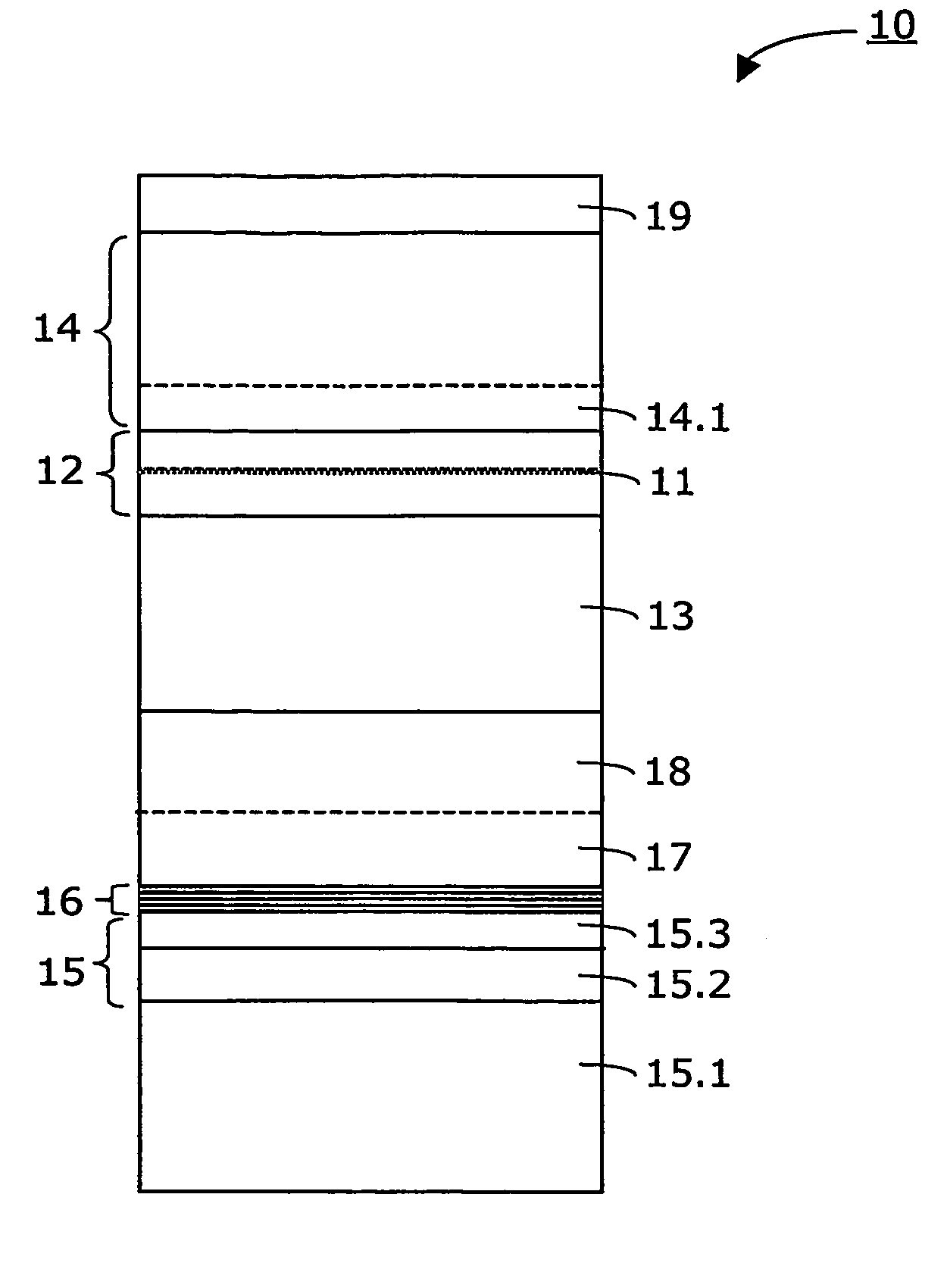
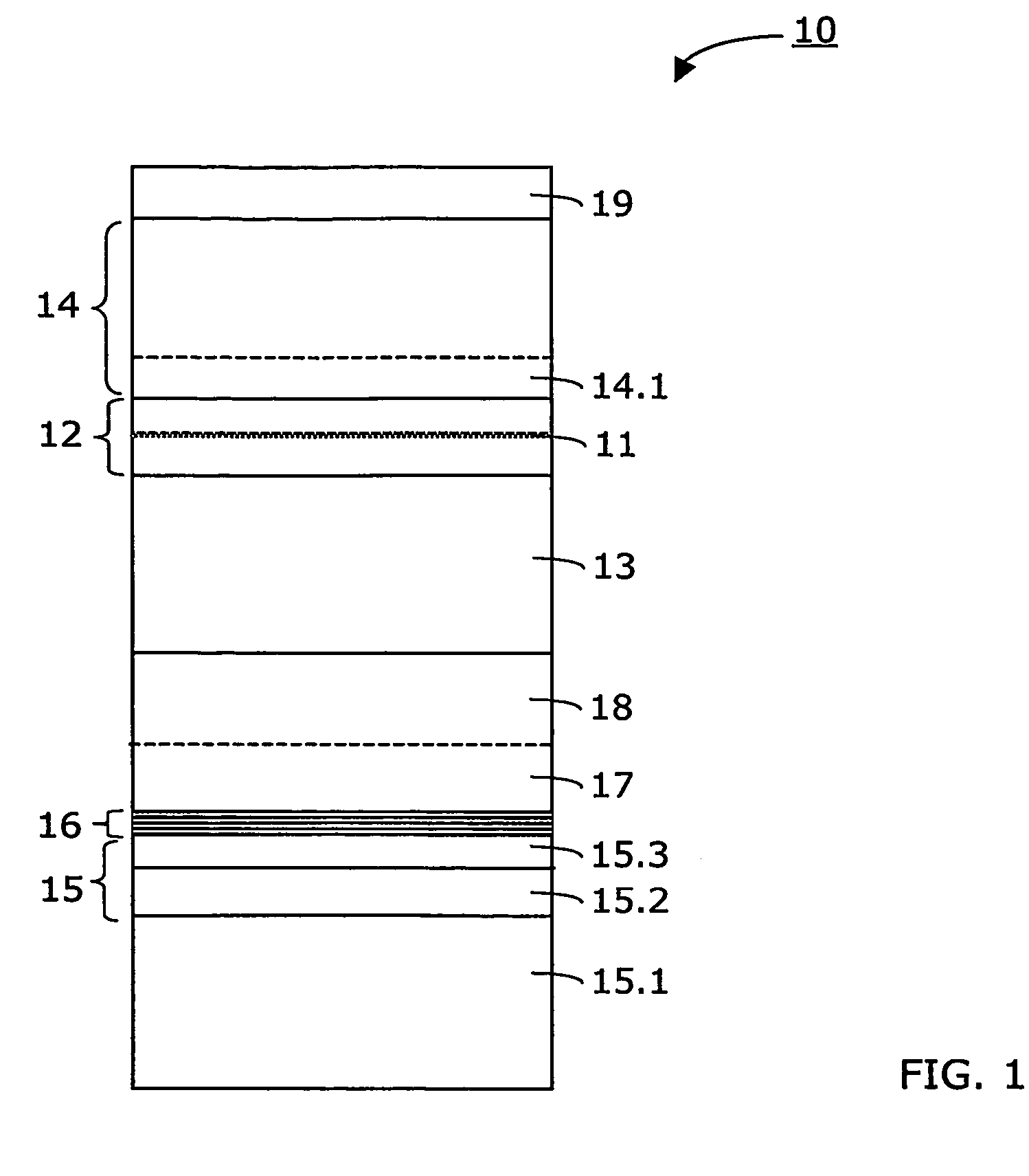
[0035]Further details of a first embodiment is given in the following table:

[0036]

ReferenceNumberThicknessTypicalof LayerMaterialDopingRangeThickness15.1Si-wafer—100-1000μm~200μm[001]-oriented, 6afterdegree offpolishing15.2SiGe (graded)—0.3-14μm~5μm15.3Ge (pure)—0.5-5μm1μm16As / Gadoped or1-3nm2nmundoped17GaAsdoped or0.2-2μm~0.7μmundoped18GaAsn+-doped,0.2-2μm~0.7μmSi 7 · 1018cm−313Al0.35Ga0.65Asn-doped,1-5μm~2μmSi 2 · 1018cm−312GaAsundoped0.2-0.4μm~0.29μm11InGaAs (strained)—5-15nm~10nmIn concentrationbetween 20-25%14.1Al0.35Ga0.65Asundoped0.1-0.3μm~0.2μm14Al0.35Ga0.65Asp-doped,1-5μm~2μmZn 5 · 1017cm−319GaAsP++-doped,0.1-0.3μm~0.15μmZn 1 · 1019cm−3

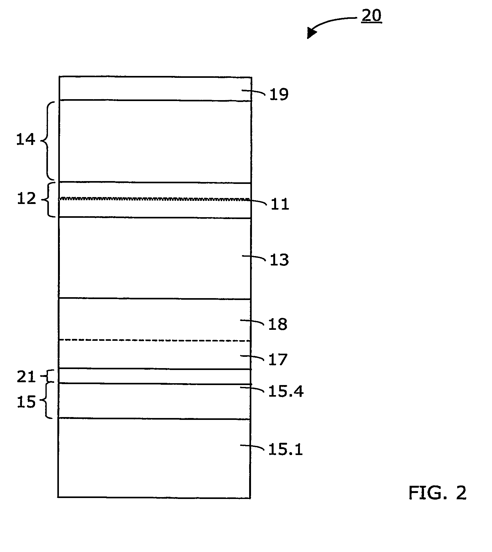
[0037]Another laser structure 20, according to the present invention, is depicted in FIG. 2. The corresponding details are given in the following table:

[0038]

ReferenceNumberThicknessTypicalof LayerMaterialDopingRangeThickness15.1Si-wafer—100-1000μm~300μmafterpolishing15.4Ge (pure)—0.5-5μm~2μm21GaAs (formed atdoped or1-3nm2nmTs1)undoped17GaAs ...

second embodiment

[0047]As stated in connection with the second embodiment, the virtual Germanium substrate 15 may comprise a pure Germanium layer 15.4 being formed directly on the Silicon substrate 15.1. The pure Germanium layer 15.4 has a thickness between 0.5 μm and 5 μm, and preferably between 1 μm and 2 μm.

[0048]Preferably, the second Gallium Arsenide waveguide layer 17 is undoped and has a thickness between 0.2-2 μm. It may have a thickness of about 1 μm, for instance.

[0049]The Gallium Arsenide waveguide layer 12 may be undoped. It has a thickness between 0.2-0.4 μm, and preferably about 0.29 μm.

[0050]Several metal organic chemical vapour deposition process steps are carried out when forming the active laser structure. Advantageous results are achieved if the active laser structure comprises an InGaAs quantum well laser structure. Preferably, the active laser structure comprises an InGaAs / AlGaAs / GaAs quantum well laser structure with a compressively strained InGaAs quantum well 11.

[0051]Accordi...


PUM

PropertyMeasurementUnit
thicknessaaaaaaaaaa
thicknessaaaaaaaaaa
thicknessaaaaaaaaaa

Abstract

Method for making an InGaAs / GaAs quantum well laser (10) on a Silicon substrate (15.1). The method comprises the steps:Formation of a virtual Germanium substrate (15) on the Silicon substrate (15.1) by means of a low-energy plasma-enhanced chemical vapourdeposition (LEPECVD). The virtual Germanium substrate (15) comprises a pure Germanium layer (15.3).Formation of a Gallium Arsenide structure on the virtual Germanium substrate (15) by means of a metal organic chemical vapour deposition process. The metal organic chemical vapour deposition process comprises the steps:formation of a first Gallium Arsenide layer (16) on the virtual Germanium substrate (15) at a first substrate temperature (Ts1),formation of a second Gallium Arsenide waveguide layer (17) at a second substrate temperature (Ts2), the second substrate temperature (Ts2) being higher than the first substrate temperature (Ts1) and the first Gallium Arsenide layer (16; 21) being thinner than the second Gallium Arsenide layer (17),formation of an active laser structure comprising a Gallium Arsenide waveguide layer (12) embedding a quantum well (11).

Description

[0001]This application is the US National Stage of PCT / EP04 / 09873, entitled INGAAS / GAAS LASERS ON SILICON PRODUCED BY LEPECVD AND MOCVD, filed Sep. 4, 2004, which claims priority to European Application 03020169.3, filed Sep. 5, 2003.[0002]The present invention concerns methods for making lasers, in particular InGaAs / GaAs lasers, on top of a Silicon substrate, where the laser's active region comprises a strained semiconductor layer.STATE OF THE ART[0003]It is known in the art to grow Gallium Arsenide (GaAs) on Silicon (Si) by means of an intermediate Silicon Germanium (SiGe) buffer layer. The concept of graded SiGe buffer layers was invented in 1991 by Fitzgerald et al. (cf. F. A. Fitzgerald, Y.-H. Xie, M. L. Green, D. Brasen, A. R. Kortan, J. Michel, Y.-J Mii, and B. E. Weir, Appl. Phys. Lett. 58, 811 (1991)). Such graded SiGe buffer layers are used as so-called virtual substrates (VS) for applications in the area of high-speed electronics and for the integration of compound semico...

Claims


Application Information

Patent Timeline
Patent Type & Authority Patents(United States)
IPC IPC(8): H01L21/00H01L21/20H01L21/205H01S5/343
CPCB82Y20/00H01L21/02381H01L21/0245H01L21/02463H01S5/34313H01L21/0251H01L21/02546H01L21/0262H01L21/02507
Inventor VON KAENEL, HANSSAGNES, ISABELLESAINT-GIRONS, GUILLAUME JACQUESBOUCHOULE, SOPHIE
Owner DICHROIC CELL
Why Eureka
Try Eureka