
Orthopedic fusion plate having both active and passive subsidence controlling features

a technology of fusion plate and passive subsidence, which is applied in the field of orthopedic surgery, can solve the problems of disc herniation or protrusion, disc breakage or degeneration, and variety of problems or disease states, and achieve the effect of facilitating bony union and reducing the deleterious effects of subsiden

Active Publication Date: 2009-09-22
SUDDABY LOUBERT
View PDF25 Cites 30 Cited by
  • Summary
  • Abstract
  • Description
  • Claims
  • Application Information

AI Technical Summary

Benefits of technology

"The invention is a spinal fusion plate that helps stabilize bone interfaces and compensates for subsidence (when bone grafts shrink or become less stable over time). The plate has a curved metal frame and plates that can slide vertically up or down, but cannot move in other directions. The plates can be actively or passively modulated to counteract the effects of subsidence and promote bony union. The spring mechanism allows for continuous modulation of the translation plates to further mitigate against the deleterious effects of subsidence. Overall, the invention helps ensure a stable and successful spinal fusion."

Problems solved by technology

As a result, stresses acting upon the human backbone (or vertebral column) are unique in many senses, and result in a variety of problems or disease states that are peculiar to the human species.
The repetitive forces which act on intervertebral discs during repetitive day-to-day activities of bending, lifting and twisting cause them to break down or degenerate over time.
Disruption of a discs internal architecture leads to bulging, herniation or protrusion of pieces of the disc and eventual disc space collapse.
In addition, loss of disc space height reduces tension on the longitudinal spine ligaments, thereby contributing to spinal instabilities such as spinal curvature and lithesis.
One of the main causes of failure of these fusion techniques is the failure to fuse, or non-union, at the site where the bone is grafted between the vertebral bodies.
Even though many plating systems place bone grafts under sufficient compression to facilitate or even enhance bony fusion, bone grafts themselves may undergo minor degrees of resorption which causes the graft length to shorten or subside.
This subsidence in turn is detrimental to the fusion process because the osteoblasts must now bridge an ever widening gap between host bone and graft.
Ironically, rigid plating systems may actually work against the fusion process by holding host bone in a fixed position as subsidence occurs.
The trouble with most of these mechanisms is that they allow for too many degrees of movement in too many places.
Whereas the only movement necessary to counteract subsidence is movement in a unidimensional plane, many existing plating mechanisms allow for movement of the screws in several planes, amounting in essence to putting in loose screws, which defeats the purpose of a true stabilizing plating system.

Method used


Image

  • Orthopedic fusion plate having both active and passive subsidence controlling features
  • Orthopedic fusion plate having both active and passive subsidence controlling features
  • Orthopedic fusion plate having both active and passive subsidence controlling features

Examples


Embodiment Construction

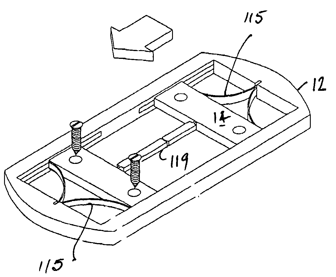
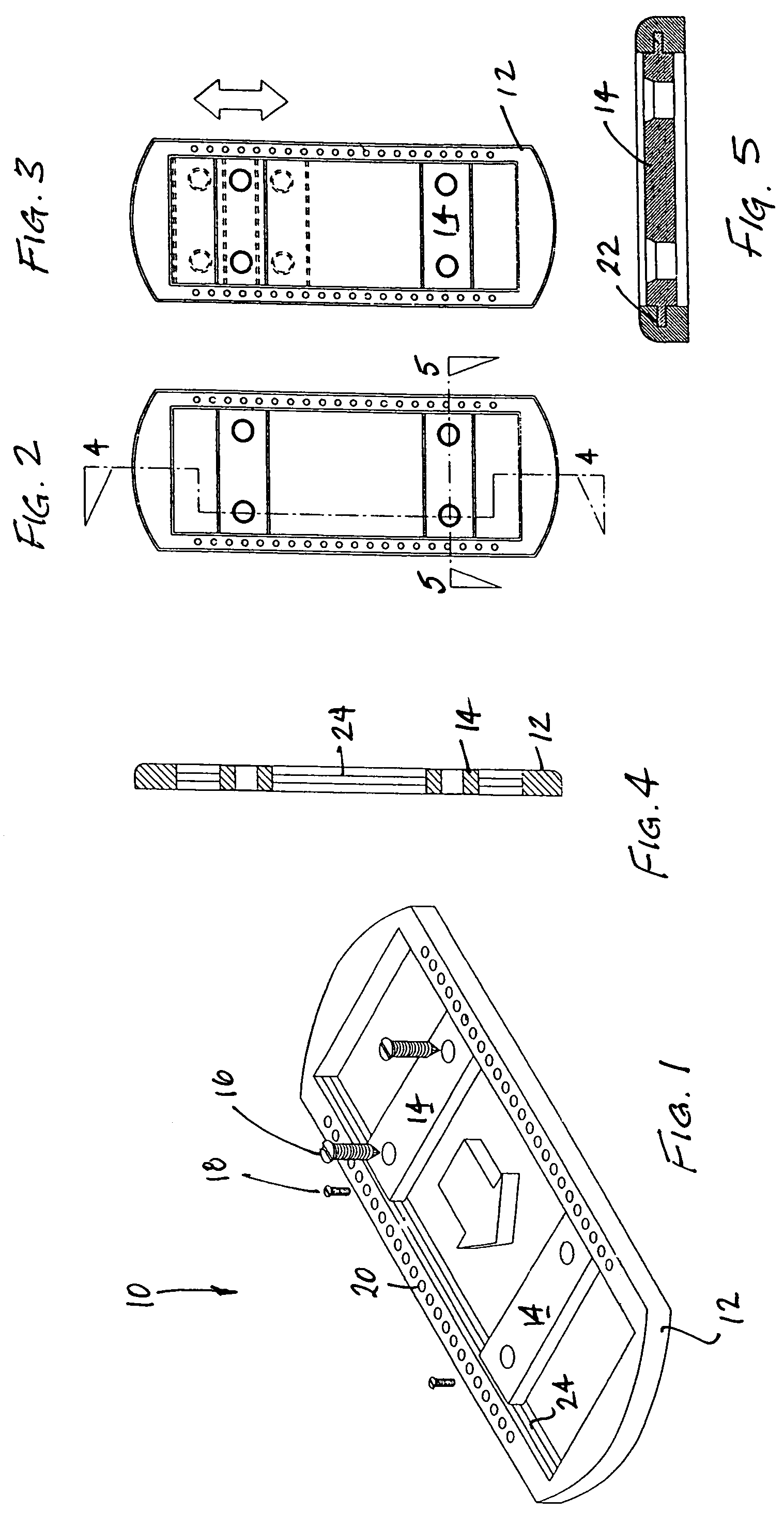
[0030]FIGS. 1-5 depict the component parts of a passive version of a translation fusion plate device according to the invention. The device 10 includes a rigid perimetral frame 12 and pair of translation plates 14. Bone screws 16 for fixing the translation plate 10 to a vertebral bone are also shown. Set screws 18 may be inserted in holes 20 to fixate the translation plate to the frame 12, should translation of one or more of the plates not be desired. As FIG. 5 shows, each plate 14 has at each end a tongue 22 which rides in a groove 24 in the facing longitudinal inner edge of the frame. Alternatively, the grooves could be formed on the plate ends and the tongues on the inner frame edges. Either way, the plate is retained within the frame opening while allowing for unidimensional translational movement, and no relative rotation between the plates, or between either plate and the frame.

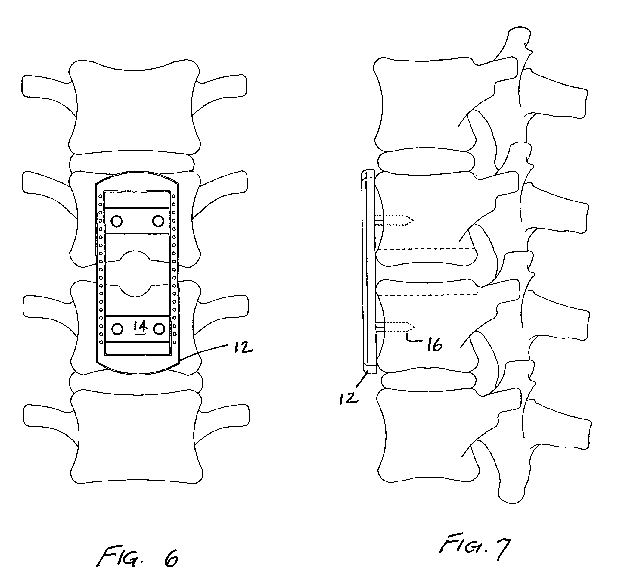
[0031]FIGS. 6 and 7 shows the passive translation plate as it appears when attached to spinal verte...


PUM


Abstract

An orthopedic fusion plate device has a rigid perimetral frame which embraces a pair of plates retained within the frame by a tongue and groove mechanism so that the plates can move in only a single dimension, toward and away from another. The device is intended to mitigate the effects of bone graft resorption and settling through either active or passive mechanisms.

Description

[0001]This application claims benefit under 35 USC 119(e) from provisional patent application 60 / 645,044, filed Jan. 21, 2005.BACKGROUND OF THE INVENTION[0002]This invention relates to orthopedic surgery and more particularly to orthopedic fusion plates designed for rigid and semirigid fixation to encourage bony union when bone grafts are used in spinal fusion techniques.[0003]Of all animals possessing a backbone, human beings are the only creatures who remain upright for significant periods of time. From an evolutionary standpoint, this erect posture has conferred a number of strategic benefits, not the least of which is freeing the upper limbs for purposes other than locomotion. From an anthropologic standpoint, it is also evident that this unique evolutionary adaptation is a relatively recent change, and as such has not benefitted from natural selection as much as have the horizontal backbones of other animals. As a result, stresses acting upon the human backbone (or vertebral co...

Claims


Application Information

Patent Timeline
Patent Type & Authority Patents(United States)
IPC IPC(8): A61B17/66
CPCA61B17/7059A61B17/8004A61B17/8085
Inventor SUDDABY, LOUBERT
Owner SUDDABY LOUBERT
Learn More