Receiver assembly and method for multi-gigabit wireless systems

a multi-gigabit wireless and receiver technology, applied in diversity/multi-antenna systems, instruments, reradiation, etc., can solve the problems of slow, or even stop, the transmission of communication, and the cost-effectiveness of converting a signal from analog to digital at such high frequencies and at such high speeds

Active Publication Date: 2009-09-22
GEORGIA TECH RES CORP
View PDF17 Cites 92 Cited by
  • Summary
  • Abstract
  • Description
  • Claims
  • Application Information

AI Technical Summary

Benefits of technology

[0014]Each antenna of the plurality of antennas can provide approximately 10 dBi of gain, an azimuth 3 dB beam-width of approximately 60 degrees, and an elevation 3 dB beam-width in a range of approximately 30 to 35 degrees, which can produce an unexpected result at the preferred operating frequency.

Problems solved by technology

Converting a signal from analog to digital at such high frequencies and at such high speeds is currently not cost effective.
Also, line of sight is required to transmit at such frequencies and speed, so an obstruction in the wireless communication can slow, or even stop, transmission of communication.

Method used


Image

  • Receiver assembly and method for multi-gigabit wireless systems
  • Receiver assembly and method for multi-gigabit wireless systems

Examples


Embodiment Construction

[0021]To facilitate an understanding of the principles and features of the invention, it is explained hereinafter with reference to its implementation in an illustrative embodiment. In particular, the invention is described in the context of being a wireless receiver assembly for operation at ultra-high frequencies and ultra-high data communication speeds.

[0022]The materials described as making up the various elements of the invention are intended to be illustrative and not restrictive. Many suitable materials that would perform the same or a similar function as the materials described herein are intended to be embraced within the scope of the invention. Such other materials not described herein can include, but are not limited to, for example, materials that are developed after the time of the development of the invention.

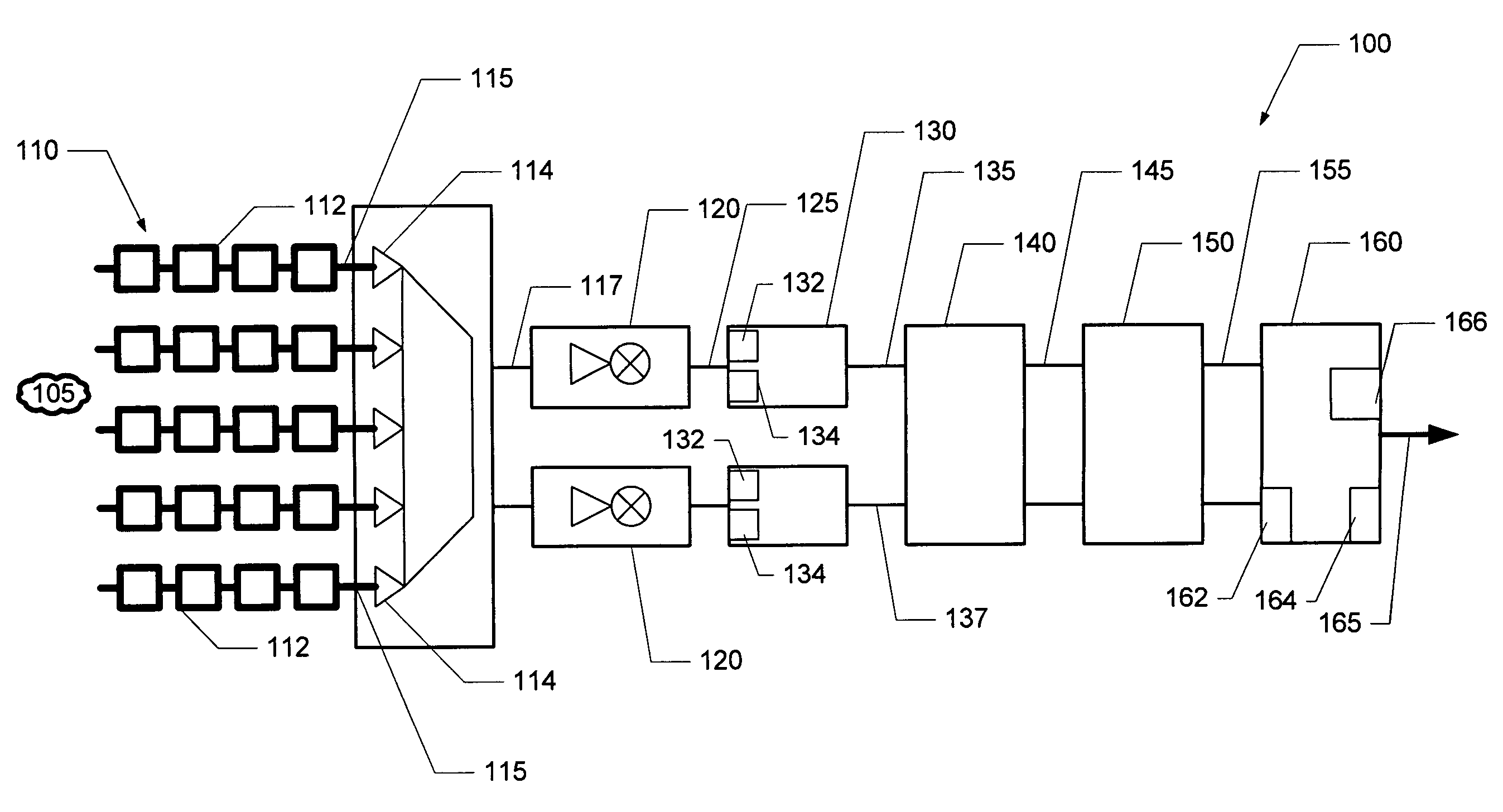
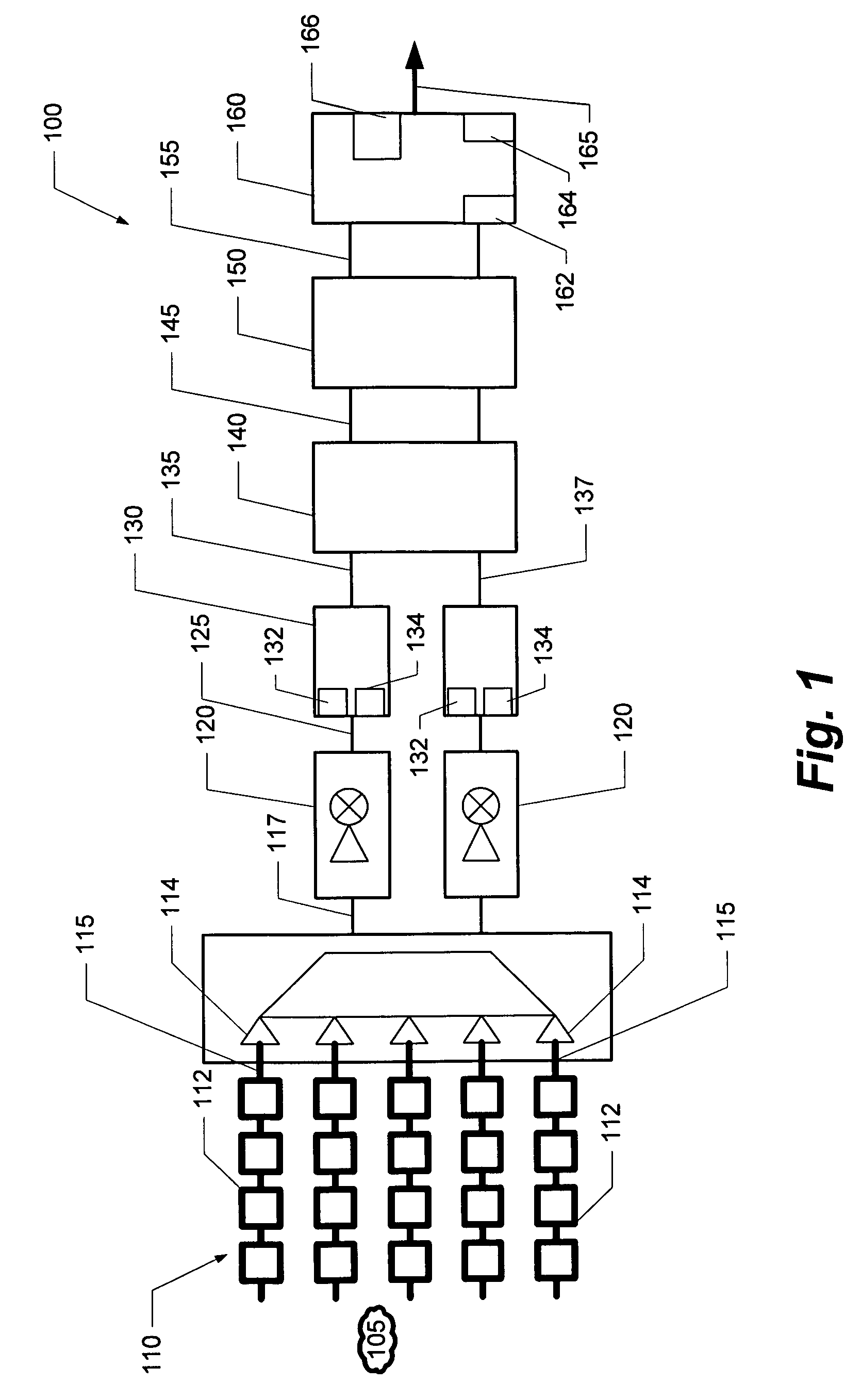
[0023]The present invention is a receiver assembly 100. The receiver assembly 100 comprises an N-array antenna assembly 110, a down converter 120, a demodulator 1...


PUM


Abstract

The present invention describes a receiver assembly for receiving an analog signal and converting the analog signal to a digital signal. The receiver assembly is, preferably, capable of receiving a signal operating at approximately 60 GHz. The receiver assembly includes a filter, a down converter, a demodulator, a latch, a FIFO, and a logic circuit. A method of converting the 60 GHz analog signal to a digital signal is also described.

Description

CROSS-REFERENCE TO RELATED APPLICATIONS[0001]This application claims the benefit of U.S. Provisional Application Nos. 60 / 666,839 and 60 / 666,840, both filed 31 Mar. 2005, and U.S. Provisional Application Nos. 60 / 667,287, 60 / 667,312, 60 / 667,313, 60 / 667,375, 60 / 667,443, and 60 / 667,458, collectively filed 1 Apr. 2005, the entire contents and substance of which are hereby incorporated by reference.BACKGROUND OF THE INVENTION[0002]1. Field of the Invention[0003]The present invention relates to communication networks and, more particularly, to architecture for a high-speed, high-frequency wireless system.[0004]2. Description of Related Art[0005]As the world becomes more reliant on electronic devices, and portable devices, the desire for faster and more convenient devices has increased. Accordingly, producers of such devices strive to create faster, easier to use, and more cost-effective devices to serve the needs of consumers.[0006]Indeed, the demand for ultra-high data rate wireless commu...

Claims


Application Information

Patent Timeline
Patent Type & Authority Patents(United States)
IPC IPC(8): H04B7/08H04B1/06G01S19/19
CPCH04B7/088H04B7/0808
Inventor PINEL, STEPHANELASKAR, JOY
Owner GEORGIA TECH RES CORP
Why Eureka
Try Eureka