Device for driving a weaving frame in a weaving machine and a weaving machine provided with one or several such devices

a technology for weaving frames and weaving machines, which is applied in weaving, textiles and papermaking, looms, etc., can solve the problems of high cost of motors, no longer supporting driving rods, and rapid wear and tear, and achieve the effect of favorable cost pri

Inactive Publication Date: 2009-09-29
N V MICHEL VAN DE WIELE
View PDF15 Cites 0 Cited by
  • Summary
  • Abstract
  • Description
  • Claims
  • Application Information

AI Technical Summary

Benefits of technology

[0014]The purpose of the invention is to provide a device for driving a weaving frame in a weaving machine in accordance with the preamble of the first claim, a device being obtained with a double-sided bearing for driving a weaving frame which will be compact, simple and at a favorable cost price.

Problems solved by technology

This arrangement requires motors having a high torque and a quick reaction time, which will render this motors very expensive.
Furthermore, the driving rod is no longer supported by bearings outside the motor, so that the reactive forces caused by the tension of the warp yarns on the weaving frame which are transmitted to the eccentric shaft through the connecting bars and levers and the driving rod will end up completely, as a load on the bearings of the drive motor.
Because of this, the bearings in the motor on the side of the output shaft will be subjected to an additional heavy load, which may cause them to wear out rapidly and to be of a short operating lifetime.
The solution as proposed in EP 1 477 598 has a double-sided bearing arrangement on the output shaft, but has the disadvantage that attaching the geared motor to the frame of the shed forming device on the one hand, and the bearing arrangement of the eccentric shaft on the other hand, will make high demands on the precision of the frame and the geared motor.
All this will increase the cost of both frame and geared motor, as well as the installation costs to connect the geared motors to the frame.
When, because of different loads exerted on different weaving frames, the decision should be made to use different geared motors and eccentric shafts with different bearings, such a frame will not allow for weaving frames having different bearings on the eccentric to change positions in their drives.
In case the geared motors are installed on both sides of the frame of the shed forming device, as represented in the FIGS. 1, 2, and 5 of EP 1 477 598, the bearing seats in the frame for the bearings on the eccentric shafts, have to be finished centrally in the frame, which is a complicated and expensive operation.
Moreover, both the connection of the eccentric shafts on the output shaft of the geared motor and the bearing arrangement of the eccentric shafts in the frame will require space inside the frame, which will prevent the frame from being made more compact or from driving more weaving frames with the same dimension of the frame.

Method used


Image

  • Device for driving a weaving frame in a weaving machine and a weaving machine provided with one or several such devices
  • Device for driving a weaving frame in a weaving machine and a weaving machine provided with one or several such devices
  • Device for driving a weaving frame in a weaving machine and a weaving machine provided with one or several such devices

Examples


Embodiment Construction

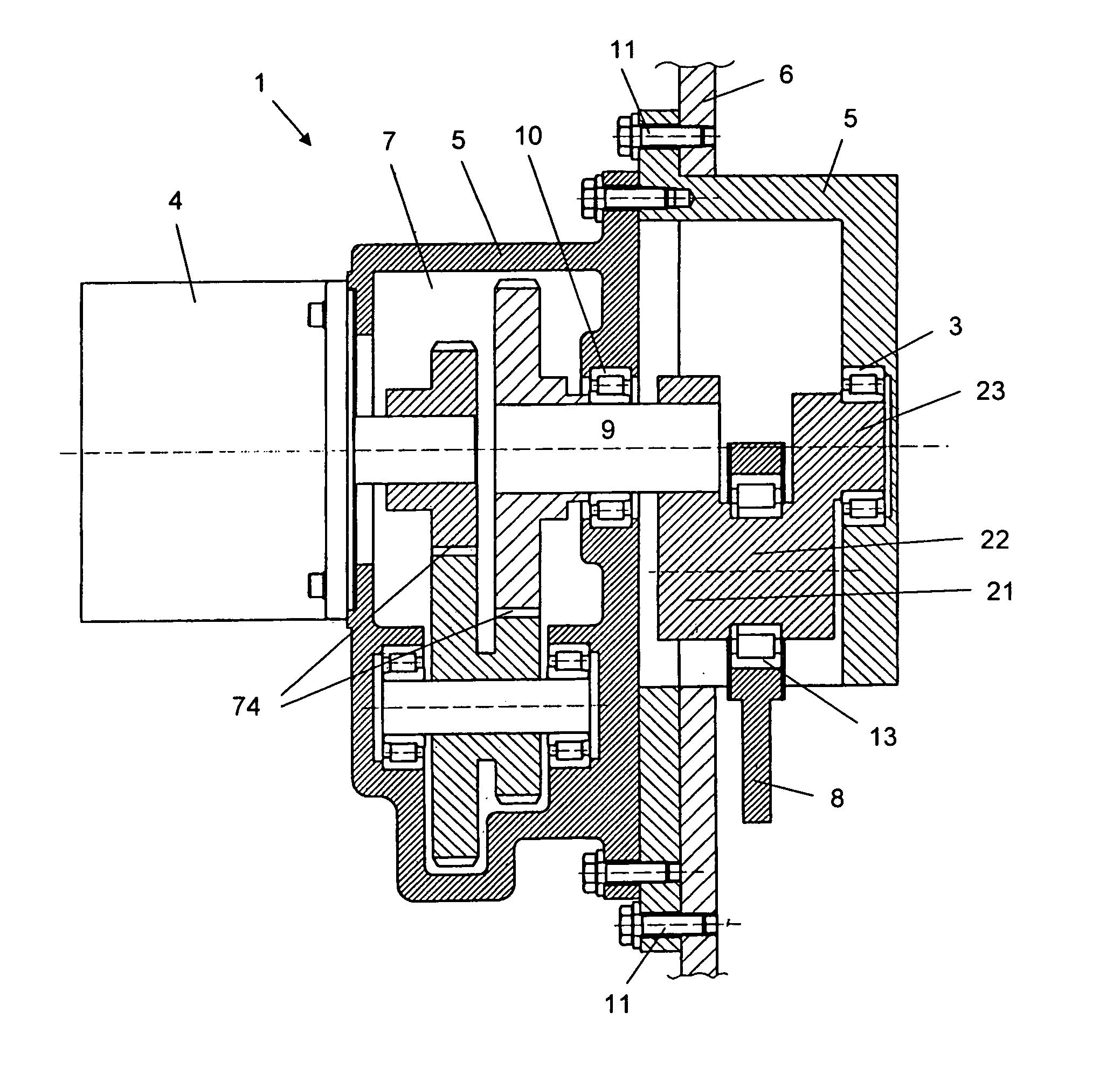
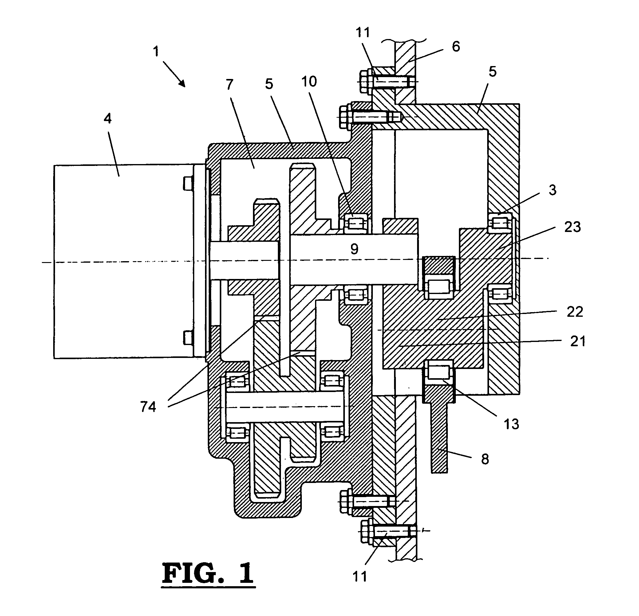
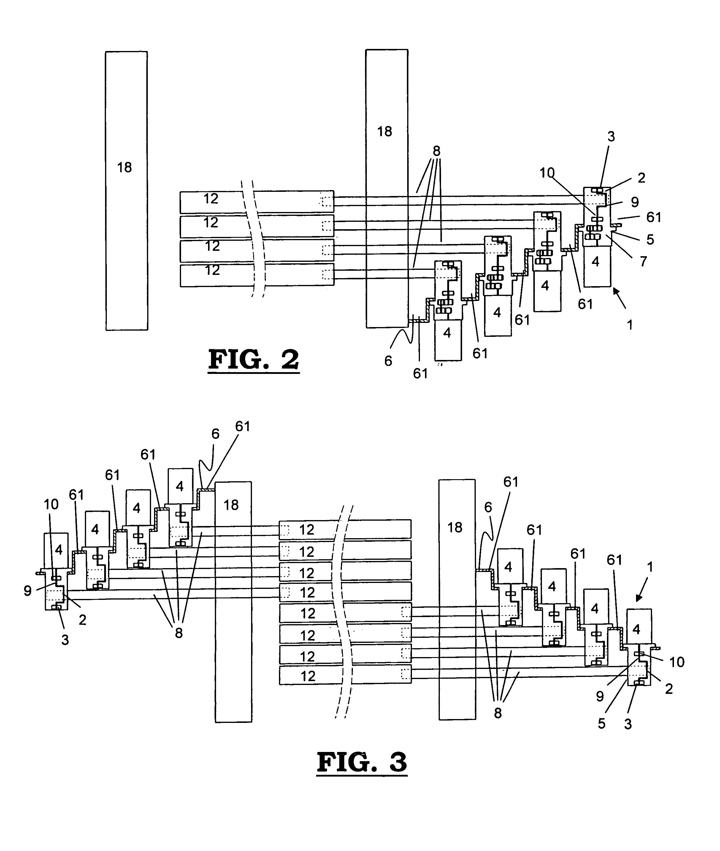
[0062]A device for driving a weaving frame in a weaving machine as represented in the FIGS. 1 to 7, is comprising a drive with a motor (4) or a geared motor (4, 7) which is provided with a bearing (10) on its output shaft (9), with an eccentric shaft (2) and with a driving rod (8) which is carried out as a driving module (1) in which the eccentric shaft (2) is supported by an abutment (3) situated in the housing (5) of the driving module (1) on the side of the eccentric shaft (2) away from the motor (4) or the geared motor (4, 7). The housing (5) of the driving module is provided to be installed on a frame (6) in the weaving machine. As represented in the FIGS. 2, 3 and 4, the frame may be provided for several driving modules (1) to be attached to it. For that purpose, the frame (6) may consist of, for instance, a base plate and an upright wall which is provided for one or several driving modules (1) to be attached to it.

[0063]A preferred embodiment consists of a driving module (1) ...


PUM


Abstract

A device for driving a weaving frame in a weaving machine, comprising a drive with a motor (4) or a geared motor (4, 7), provided with a bearing (10) on its output shaft (9), with an eccentric-shaft (2) and with a driving rod (8), wherein the drive with motor (4) or geared motor (4, 7), with eccentric shaft (2) and with driving rod (8) is provided as a driving module (1) in which the eccentric shaft (2) is supported in an abutment (3) situated in the housing (5) of the driving module (1) on the side of the eccentric shaft (2) away from the motor (4) or the geared motor (4, 7). A weaving machine which is provided with one or several of the devices.

Description

[0001]This application claims the benefit of Belgian Application No. 2005 / 0338 filed Jul. 5, 2005, which is hereby incorporated by reference in its entirety.BACKGROUND OF THE INVENTION[0002]The invention relates to a device for driving a weaving frame in a weaving machine, comprising a drive with a motor or a geared motor, provided with a bearing on its output shaft, with an eccentric shaft and with a driving rod. On the other hand, the invention relates to a weaving machine provided with one or several such devices.[0003]When weaving, warp yarns are positioned with respect to weft insertion means in order to realize the shed required to manufacture a specific fabric. Once the warp yarns have taken up their exact positions when forming the shed, the one or several weft insertion means will insert the necessary wefts through the shed which, in turn, will be pushed against the fell of the fabric by the weaving reed. Then the warp yarns will be brought into a next position in order to ...

Claims


Application Information

Patent Timeline
Patent Type & Authority Patents(United States)
IPC IPC(8): D03D51/02D03C1/00D03C5/00D03C13/00D03D51/00
CPCD03C13/025D03C13/00
Inventor VANNESTE, STEPHANDEBAES, JOHNY
Owner N V MICHEL VAN DE WIELE
Why Eureka
Try Eureka