Fluorescent lighting fixtures with light transmissive windows aimed to provide controlled illumination above the mounted lighting fixture

a technology of fluorescent lighting fixtures and light transmissive windows, which is applied in the direction of fixed installation, lighting and heating equipment, light source combinations, etc., can solve the problems of increasing eyestrain, wasting light usage, and too much uplighting, so as to reduce undesirable cave effects and avoid excess light wasting

Inactive Publication Date: 2009-09-29
PHILIPS ELECTRONICS NORTH AMERICA
View PDF4 Cites 47 Cited by
  • Summary
  • Abstract
  • Description
  • Claims
  • Application Information

AI Technical Summary

Benefits of technology

[0019]It is therefore an object of the present invention to provide a fluorescent lamp fixture which controls uptight to a desirable level, with

Problems solved by technology

The cave effect causes a glare-filled, enclosed effect, which increases eyestrain.
However, too much uplighting is inefficient and wasteful, not reflecting a large portion of emitted light back to the space below the fixture.
To provide uplight, it is known to have an open top, which wastes light usage, as much of the light is not reflected back to the space below the fixture.
In addition, in general, however, lamp fixtures with open top

Method used


Image

  • Fluorescent lighting fixtures with light transmissive windows aimed to provide controlled illumination above the mounted lighting fixture
  • Fluorescent lighting fixtures with light transmissive windows aimed to provide controlled illumination above the mounted lighting fixture
  • Fluorescent lighting fixtures with light transmissive windows aimed to provide controlled illumination above the mounted lighting fixture

Examples


first embodiment

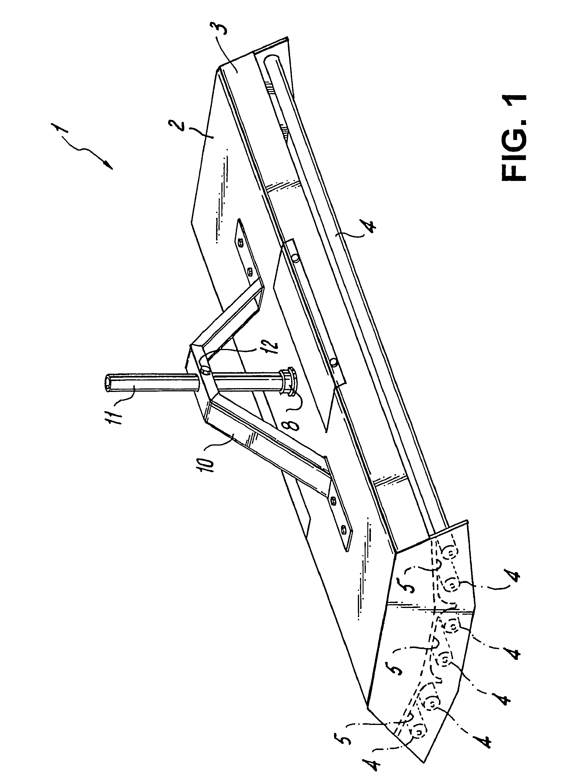
[0037]FIG. 1 shows this invention, wherein fixture 1 uses no lenses. Fixture 1 has six straight fluorescent tubes 4 within housing 2 with shortened oblique walls 3. Central concave reflector 6 is aimed straight down while side reflectors 5 are angled obliquely and have no curved section (or a very truncated one) at their distal ends. Reflector surface finish can vary, however a white finish, a specular reflector, or an enhanced specular reflector surface with 95% reflectivity are currently offered.

[0038]Pendant pipe 11 is used to attach fixture 1 to a ceiling structure; it also carries wiring within. It is mounted in hub 8 and is located accurately by trapezoidal pendant bracket 10 and secured by pendant screw 12. However, pendant bracket 10 is usable on any type of suspended light fixture, to stabilize the fixture in place.

second embodiment

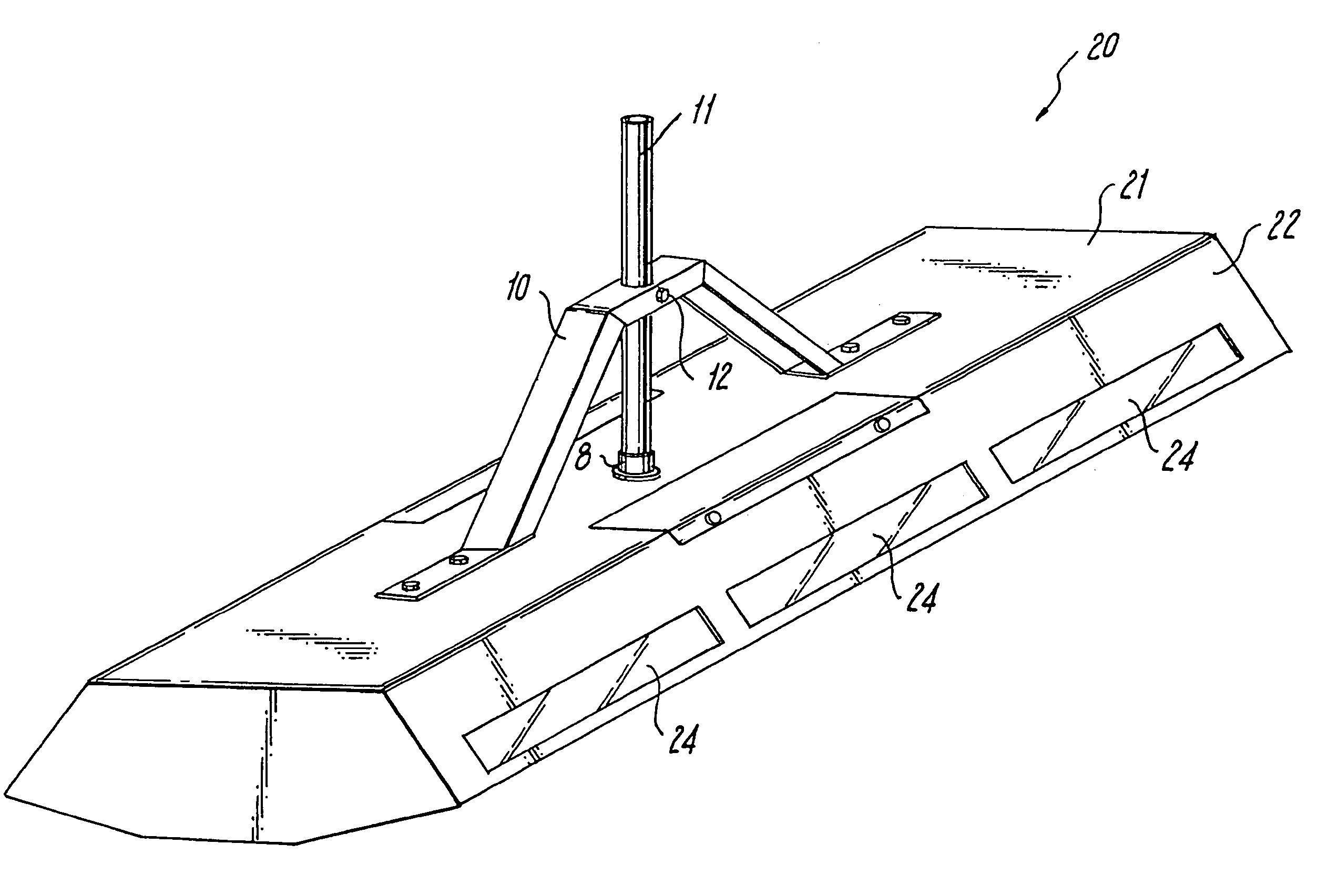
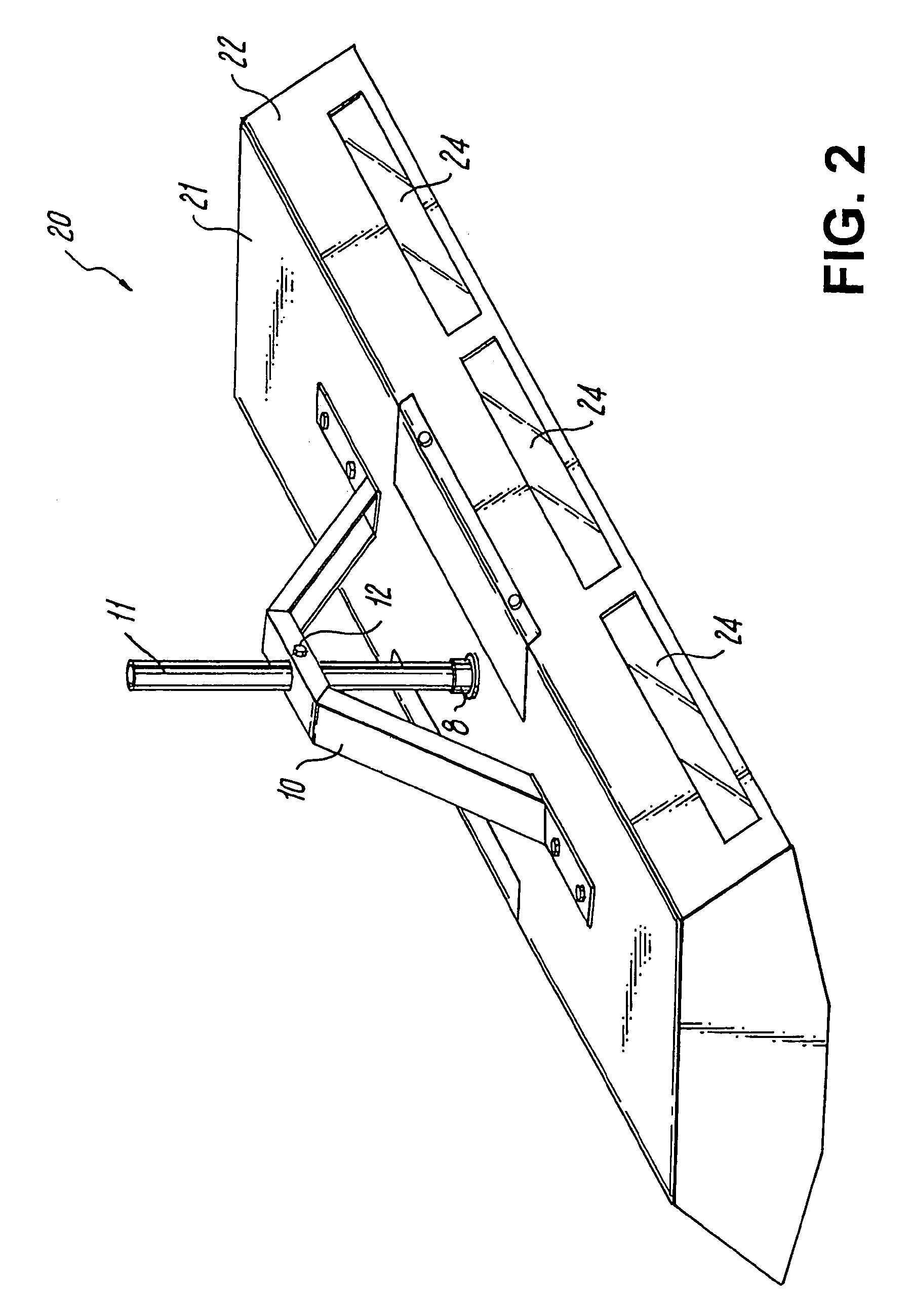
[0039]In a second embodiment, fixture 20 of FIG. 2 has housing 21 with full oblique walls 22. Walls 22 have three rectangular windows 24 with flat high efficiency lenses to permit a controlled amount of uplighting.

[0040]Fixture 20, as shown in FIG. 2, includes housing 21 which has an elongated horizontal top surface with side edges along an elongated length of the top surface and edges at opposing ends of the top surface. Opposing oblique side walls 22 have flat surfaces extending from the side edges of the top surface and the opposing oblique side walls are shown to flare at an angle downwardly and outwardly from the side edges of the top surface. Opposing end walls extend downwardly from the edges at the opposing ends of the top surface and the oblique side walls and end walls join to form a downwardly facing opening in housing 21. Referring to FIGS. 2-5, a plurality of generally downwardly facing reflectors within housing 21 extending the length of the housing, and a plurality of...


PUM


Abstract

A fluorescent light fixture with light transmissive windows aimed to provide controlled illumination above the mounted lighting fixture includes a housing having an elongated horizontal top surface with side edges and edges at opposite ends of the top surface. Oblique walls extend from the side edges of the top surface, and flare downwardly and outwardly from the side edges. First and second end walls extend downwardly from opposite ends of the top surface, the oblique walls and end walls joining to form a downwardly facing opening in the housing. Fluorescent light bulbs are mounted parallel to each other in the housing, so that light from selected light bulbs is reflected generally downwardly. The oblique walls include a plurality of spaced windows configured to direct a controlled portion of light from one or more light bulbs in a generally upward direction to provide indirect lighting.

Description

BACKGROUND OF THE INVENTION[0001]This application claims priority to co-pending patent application Ser. No. 11 / 430,347, filed May 9, 2006, the entire disclosure of which is incorporated herein by reference. This application is owned by the owner of application Ser. No. 10 / 750,391, filed Dec. 31, 2003, now issued as U.S. Pat. No. 7,070,303, the entireties of which are also incorporated herein by reference.[0002]1. Field of the Invention[0003]The present invention relates to electrically powered lighting fixtures including fluorescent lighting fixtures adapted for use indoors or beneath a ceiling.[0004]2. Discussion of the Prior Art[0005]In order to make a large area visually comfortable, downlight fixtures often include some uplight capabilities, to reduce the “cave” effect caused by ceiling fixtures being too intense for the viewer to see the ceiling beyond the fixtures. The cave effect causes a glare-filled, enclosed effect, which increases eyestrain.[0006]However, too much uplight...

Claims


Application Information

Patent Timeline
IPC IPC(8): F21S4/00
CPCF21S8/06F21V15/01F21V7/0016F21Y2103/00F21Y2113/00
Inventor KASSAY, CHARLES E.KASSAY, SUZANNE M.KASSAY, MARC A.KASSAY, JOHN P.
Owner PHILIPS ELECTRONICS NORTH AMERICA
Why Eureka
Try Eureka